|
Build Log, Day 25 (02.22.2005)
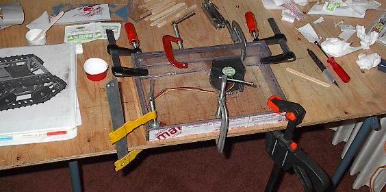
| Today is a real hodge-podge of a build day. Christina came over, so for the first time in a long time we actually have all the components in one place. While she irons out some bugs in the software, I just kind of do odd jobs for a few hours. Later on tonight we'll get in the first real test of the system. For now, I started off with some gluing. This picture shows the last of the enclosure pieces getting epoxied into place. I still haven't attached the exhaust diffuser, but other than that, it's all here. |
 |
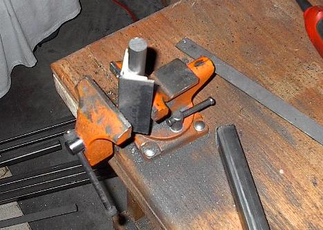
| Here I'm back out in the garage checking out a theory of mine. See, when the Teflon sheet got here, it was all warped. I thought it had been damaged during shipping, but I found that it was actually really easy to plastically deform. I got it back into shape pretty easy. So, if I could get it flat, what's to stop me from forming an angle? I cut a scrap piece, and I'm going to try to shape it into a right angle. Here, I've pressed the Teflon between some angle iron and 3/4 inch rod in the vice. It bends pretty easy. |
 |
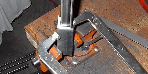
| After it had taken the general shape, I replaced the rod with some square tubing, and clamped it back down. If this works, I'll clean up the steel and bend all the glides this way. I'll leave it here for a while to set up. |
 |
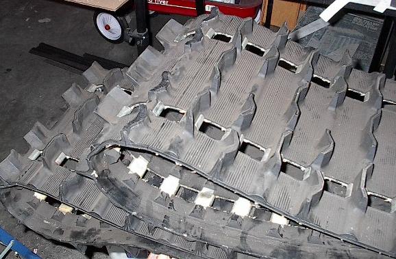
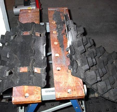
| Now I'm moving on to the track. See what I mean about being all over the place? Anyway, I've trimmed back a row of four paddles. I'm going to cut the track along that line and lay it flat so I can work with it. That is the hardest line on the whole thing to cut, but it will sever the steel clips along the inside of the track. This should allow me to actually weld it back together after I get it cut to the dimensions I want. |
 |
| I clamped it down and went after it with the jigsaw. This was really slow going. This is about an hour of work, counting lots of breaks to let the saw cool off. The rubber starts to melt, and the molten rubber coats the saw blade. Rubber on rubber causes a lot of friction and heat, so the saw motor and the track get really hot. Furthermore, the track has some kind of composite reinforcement (probably fiberglass) running right where I'm trying to cut. This is going to be rough going (and it only gets worse). |
 |
| This shows you just how far I can get in one cut. I started with a cooled jigsaw, and cut until it overheated. Not a lot of progress, but it's the best I'm able to do right now. |
 |
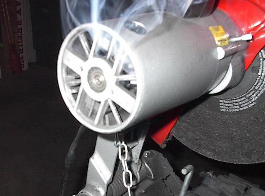
| Well, the jigsaw was going so slow, I figured I'd bust out the big guns and just do this thing. That was, for the record, a bad idea. You can't really tell, but at the moment I took this picture the chop saw was actively on fire. I'm not entirely sure what was in there that was flammable, but it really burned. I couldn't blow it out, and even holding my glove over it didn't kill it. I still do not know if the chop saw is salvageable. On the plus side, the track is cut. |
 |
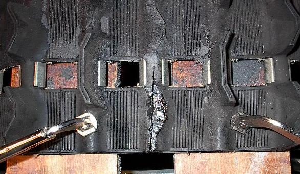
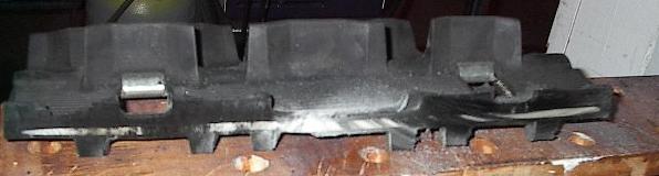
| See? Cut all the way through. It was a nightmare getting this done. I'm going to have to find an alternative for cutting the interface portion of this track, but I'm sure I'll come up with something. There was just so much friction that it totally overloaded whatever motor was cutting it. It also put up some terrible fumes as the rubber vaporized. There has to be an easier way. |
 |
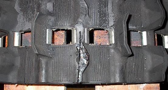
| You can see here the cut surface. The white line is a rod of something (fiberglass or some strong plastic) that was really tough. It goes all the way through, but there are parts where it looks black because of scorching or rubber that has melted over it. |
 |
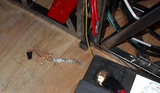
| I spent over two hours making a 15 inch cut, I caught my abrasive cut off saw on fire. It had already been a somewhat stressful build day. Then this happened. It may not look like much, but it's bad. Those two red wires used to be crimped into that silver contact laying on the plywood. While I was wiring, they came loose. That isn't supposed to happen. The crimps in the electrical system are supposed to be really strong. This one wasn't. If they're all this bad, the electrical system will be a complete loss. There isn't really a good way to test this short of just pulling on all the wires really hard, and I just can't bring myself to do it. I'll re-crimp this one (which is no small task) and move on. |
 |
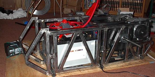
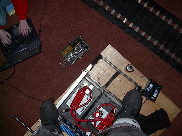
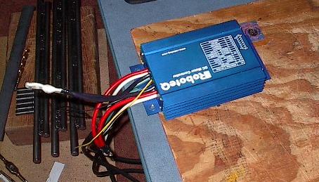
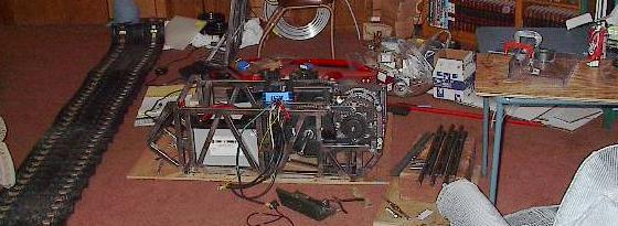
| I unwired the batteries, unbolted the speed controller, routed the wiring out, got the speed controller to my work table, fitted a new contact (not a spare, one from my charging system), crimped it again, wrapped the wire, and fitted the contact into the connector. Then I got everything back into the chassis, rewired, connected, and happy. Here it is all put back together. Note the big wire sticking out the top -- that's a kludge-job to make it work with only two batteries instead of three. Also note the two six volt batteries on the left. I haven't yet mounted my 12 volt electrical system. Finally, you can see the black wire running from the middle of the robot, along the ground, and out of the picture. This is plugged into my laptop, which we'll use to test this beast for the first time. |
 |
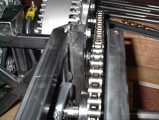
| I had a feeling this picture might come out this way. You can't even see blurring in my chop-saw blade with this camera, so there isn't any evidence of motion here either. Oh well, you'll just have to take my word for it -- the motors go when we tell them to! They squeak a little bit (both only in the clockwise direction), and the drive train on the near side shifted (this is unacceptable, but easily fixed), but all in all, seeing this thing finally spring to life was a real treat. |
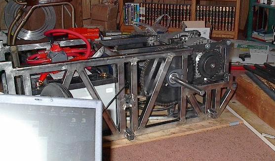 |
| Here's a close up of the misalignment. The sprocket didn't budge on the axle, but the axle drifted to the right (in this picture -- actually the robot's left). I'll fix this up next time everyone's up (it'll take some hammering) and put some real torque on the set screws. That should take care of everything. |
 |
| Well, I'm back to work on the track. Christina (you can see her knees here) is going to spend some time playing around with the robot and her software, but I've still got a lot of other work to do. |
 |
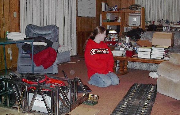
| Christina opposed having her picture taken so much I just had to snap another one. Yep, that's the girl I get the pleasure of spending countless hours robot-building with (she's a Nintendo fan, can you tell?). Note the piles upon piles of textbooks on the table, binders of robot documentation, cat 5 cable strung across the room, the tiny Gundam models way in the back, and the whiteboard (at the time, covered in cryptography algorithms and snippets of C++). It's the natural habitat of the geek and engineer. You can even see the mace on display on top of the computer table hutch. A nice little snapshot of my life, all in all. |
 |
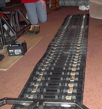
| In fact, we've gotten the room so thoroughly stocked with useful tools and robot bits, you might even say that there isn't anywhere left to walk. Well, that's simply untrue. The robot itself makes a very effective sidewalk. |
 |
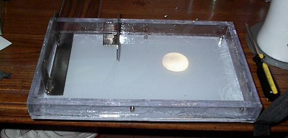
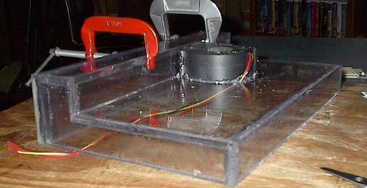
| Well, time to stop goofing off with the camera and get back to work. The glue has set up enough by now that I can start moving enclosure pieces around, so I'm going to do a final fit check. Here's the bottom of the box, with custom-made hard disk mounts, all ready to accept components. |
 |
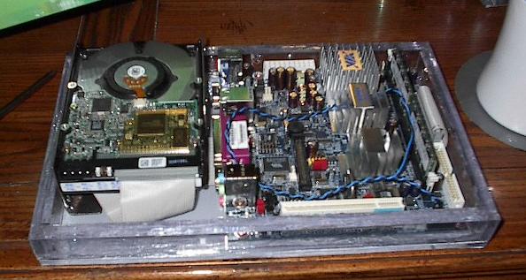
| Here it is with the hard disk, VIA board, ram, and IDE cable loaded up. I'm a little nervous running the IDE cable underneath the processor dies, but I can't bring myself to run it over the top of the adorable little computer. This is going to be right at the front of the robot, and I want everyone to see it. |
 |
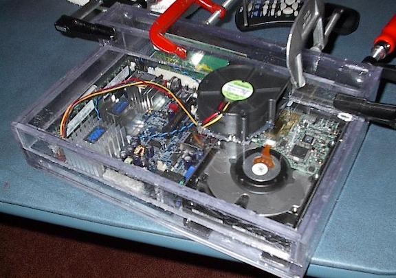
| Now I've added the wireless card, the top of the box, and the blower (which has become one with the top of the box). It's tight, but it all fits. I also checked for room for the serial cable, power supply, and power cables, and they'll all fit. This thing looks great. Now I just need to figure out how to bolt it together (not that I didn't plan for this, I'm just going to try to come up with a better option). |
 |
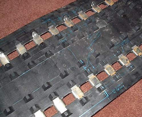
| Once again, back to the track. I've taken a blue gel pen and drawn out what I'm going to cut as well as written myself a few design notes. I'm going to cut into each tread a tongue-and-groove kind of interface, which should give me a lot more seam length to epoxy but also allow me to inset some pins for strength. |
 |
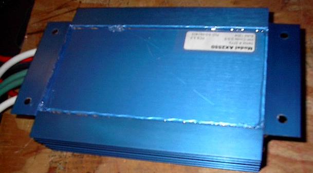
| It really takes some work to get this thing out of the robot once it's wired in. On well, yet another thing on my "to do" list was to seal up the speed controller, so I had to get it out. I'm going to just go after this little thing with a hot glue gun to make it more water resistant. It won't be perfect, but it should help protect it from the elements. |
 |
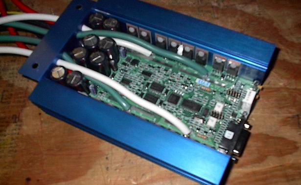
| My curiosity finally got the better of me. This is what the inside of a $500 speed controller looks like. I wasn't going to take it apart for fear of hurting the cute little thing, but who was I kidding? I had to take a look. |
 |
| It was a fairly simple matter to put it back together and seal up the seams. Water can still get in through the buttons, screen, and cables, but this will go a long way to keeping it dry. Because it's in the single most protected part of the robot, it doesn't have to be perfect. |
 |
| I think at this point the glue had set up enough that I was ready to apply a little more to the VIA box. Here, I've epoxied a few tiny cracks in the seal, and reinforced the critical seams. One more gluing (on the bearing surface, for a good seal), and the VIA box should be pretty much done. |
 |
| It's getting late, Christina has crashed, so I think I'd better hit the hay as well. I did a lot of different things, we got a good test in, and we made quite a bit of progress. Despite some significant setbacks early on, I think today was alright. Like I said, a real hodge-podge of a build day, but we got a lot of stuff done that needed to be done. |
 |
| End, Build day #25 (02.22.2005) |
| Progress: |
First major test -- successful. More VIA box gluing, cut and marked the track, burned chop-saw, checked electronics fit, sealed speed controller. |
| Time: |
10 hours |
| Total Time: |
141 hours |
| Next Steps: |
Finish the axles, build battery mounts, wire 12V system, lots of other stuff. |
| Status: |
Still behind schedule |
|