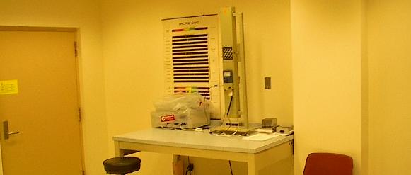
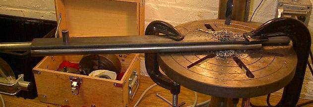
| Every Wednesday, I work in the mechanical engineering lab at Henry Cogswell College training the current lab manager on campus in the use of all of the equipment. This week, we're conducting the forced and free convection experiment, using this device. I could go on for hours about it (that's my job), but suffice it to say that it takes about an hour to collect a single point of data. It just takes a long time for everything to reach equilibrium. In any case, I had time to kill between readings, so I brought in the axles to get the drill press treatment. |
 |
| I just don't trust my skills with a hand drill to not only drill a half inch hole in six precise locations, but then to drill a variable diameter hole on a curved surface that intersects it. But I'm getting ahead of myself, we'll get to all of that later. Here, I'm drilling holes in a chunk of quarter inch steel left over from my table. This will be a template. |
 |
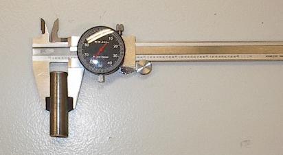
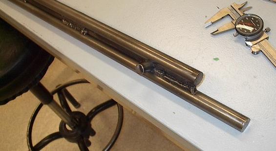
| Speaking of that half inch hole, I have a problem. I bought a half inch rod from the steel mill, I cut it up, and I figured I'd just drill half inch holes for it. Well, it's a good thing I decided to double check this thing. For those of you early-adapters who can't read an analog dial caliper, that's 0.560 inches in diameter, nearly a sixteenth of an inch too big. |
 |
| Here's a picture of one of the half inch holes I'd already drilled. I have a nice, burly, titanium coated half inch drill bit just for this. Unfortunately, I need holes that are slightly larger than half an inch. Oh well, I have some much lower quality bits I picked up at a tent sale that I can use. Time to start enlarging holes. |
 |
| Alright, one 9/16 hole, made to order, and things are fitting. They're fitting really well, too. The tightness is just about perfect, and I'm really happy with the alignment. One pin down, five to go. |
 |
| And now the template really comes into play. I used it before to get the hole started nicely, but now it measures out the exact span. There are two holes in the template, exactly the right distance apart that a pin will glide along 0.125 inch thick Teflon glides mounted to chassis members that are 14 inches apart. Now I just pin in the end that I've already drilled, and the other end should automatically line up just right. |
 |
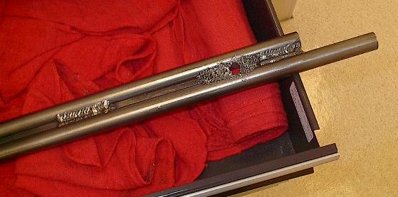
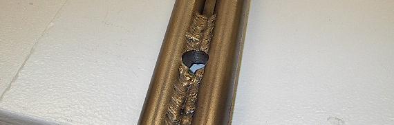
| A quick check of the hole surface tells us some really nice things. You cannot see a seam between the square and round bars. This is fantastic. This means that when I welded these together, the heat penetrated through and melted the steel all the way in, forming a bond all the way through. This should be very strong. |
 |
| With those two holes down, the first axle has both of its pins. It still needs more work, but this is a great start. |
 |
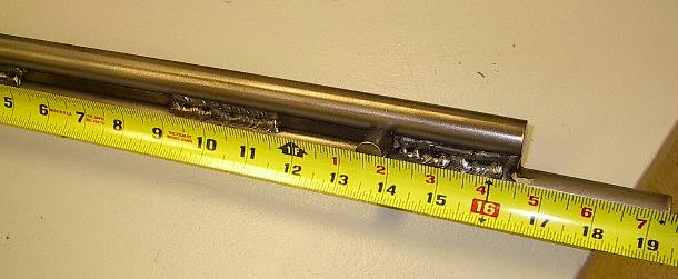
| A check of the final distance shows a total constrained distance of 13 13/16 inches. This means that each Teflon glide will need to wear down 1/32 on an inch to accommodate the axles. This is no problem. |
 |
| I'll spare you the gory details of the second axle, as they're remarkably similar to the first one. Two down, one to go. |
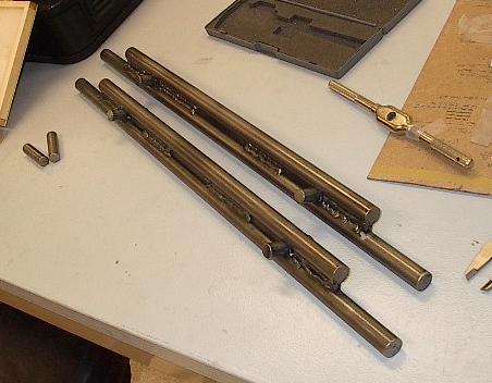 |
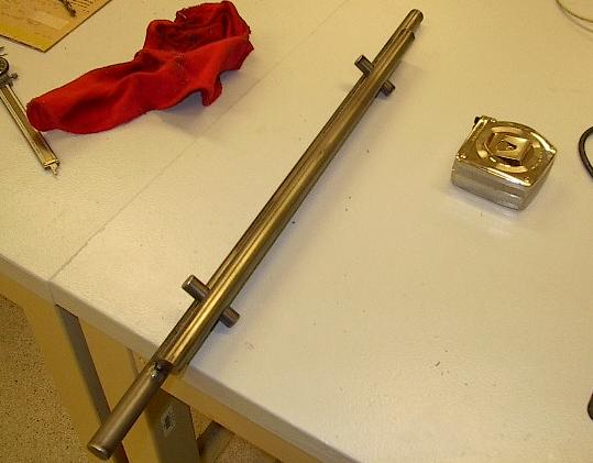
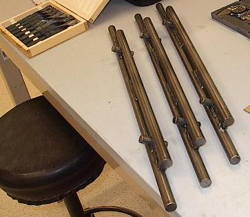
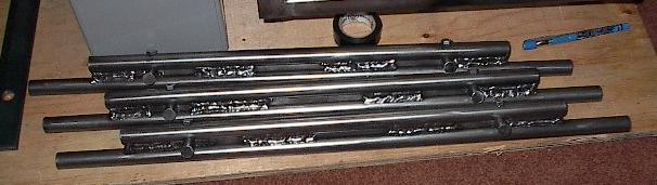
| Lather, rinse, repeat. Here's all three with their pins. Now I need to get to work on the bolt holes (wouldn't want my nice little pins falling out). |
 |
| Each assembly will have a hole drilled though it thusly. This should be done with a #7 drill bit. I didn't have any of these on hand, but they measure up at 0.201 inches, and this bit is a good 0.21-ish, which should be close enough for my purposes. Then, I'll remove the pin and enlarge the top portion of the hole to a full quarter of an inch. Then, I'll just tap the hole in the pin, and I'll be able to bolt the pins into place nice and secure. |
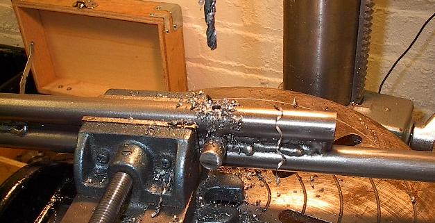 |
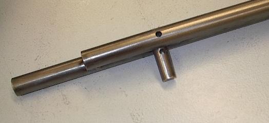
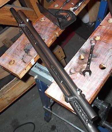
| Here you can see the hole goes all the way through the top of the axle and the pin. Should line up absolutely perfectly in the final assembly, too. |
 |
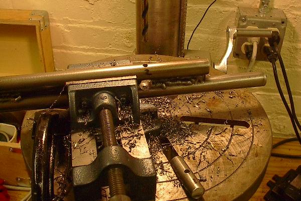
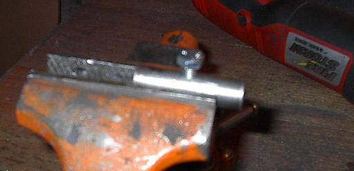
| You can see here how I've removed the pin and set up a larger drill bit. I'll use this to enlarge the top of the hole. If I didn't do this, the entire hole would be tapped, and the bolt wouldn't compress anything. |
 |
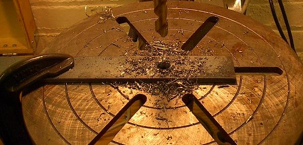
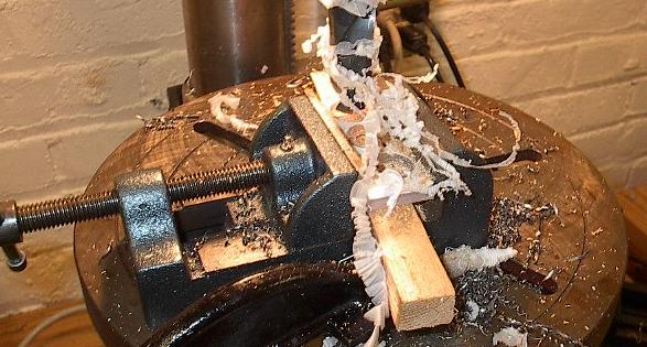
| As long as I was working on the drill press, I thought I'd drill three holes into this little Lexan plate, which will support the flexible tubing for the heat exchanger. Nothing very impressive here -- three 7/8 inch holes and some very unusual "sawdust". |
 |
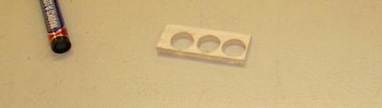
| Here's the finished result. Looks rather like a set of Lexan knuckles, but it should provide a nice junction for the heat exchanger. |
 |
| Well, things took longer than I thought, and they started arming the security system in the building, so I packed it up and took off. Here I am tapping the holes I drilled in the pins, but I'm back in the garage. You can tell by the steel grit everywhere and the poor lighting. |
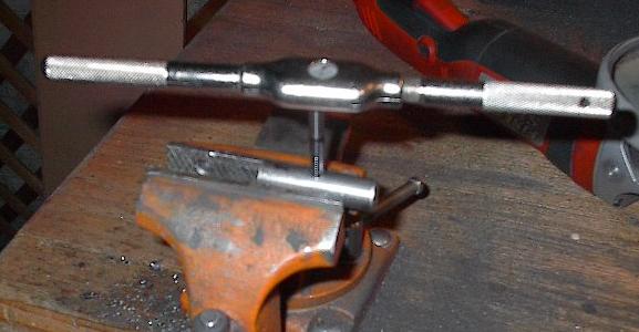 |
| There it is -- my first tapped hole. I've cleaned threads before, but never actually cut my own. It went pretty well, and the bolt rides nice, snug, and even on the treads. |
 |
| Here's the first axle, drilled, tapped, and bolted into place. |
 |
| All three axles, done. I had some trouble tapping a few of the holes -- if the tap gets started uneven, it gets off to one side of the hole and binds up. I didn't need the holes tapped all the way to the bottom, so this never caused a real problem. I'm done here for the day, time to go to bed. |
 |