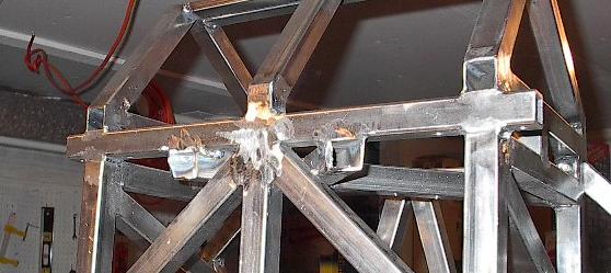
| Today, I started out by grinding down a couple of the rough edges and ugly welds left over from yesterday. After trimming these few rough edges down, I should be ready to get started welding in the last few members of the chassis. I shouldn't have too much trouble finishing up tonight. |
 |
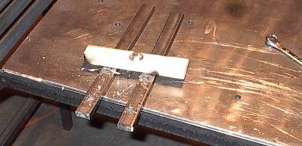
| I've decided to change my approach to mounting my electronic speed controller. I wasn't sure how well the outer casing of this component was going to be made until I got it delivered, so I assumed the worst and designed an enclosure for it. After seeing it, I'm pretty sure that I can epoxy all of the seams to make it water resistant. This means I can just bolt the controller into the chassis and I don't need to worry about the solid steel plate backing or some of my clearance issues. It also means that I had to make sure that there were members for it to bolt to. To this end, I'll be using these two pieces of steel in the place of a third "X" shaped structure in the middle. First, however, I'll need to drill some holes. |
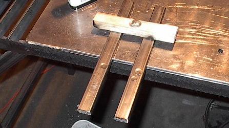 |
| Here they are drilled. I've drilled big, 3/8 inch holes here even though the bolts will be significantly smaller. The reason for this is that I do not actually have the speed controller right now. Christina is using it for some software development, so I won't be able to use it to line up the mounting holes just right. With larger holes in the support members, I can take the speed controller at a later date, and weld the weld nuts into exact alignment using the actual controller as a reference. |
 |
| Before I jump right into welding up the final members of the battery compartments, I thought I'd take one last battery fit check. I have to do this with just two of the batteries, as the third (the leaking one) was picked up by UPS this afternoon. Northern Arizona Wind and Sun has been great about the whole thing so far. Of course, I won't be able to give the final word until all the bills come in, but so far they've taken care of me in a very timely manner and I may even escape the ordeal without losing too much time. |
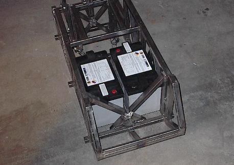 |
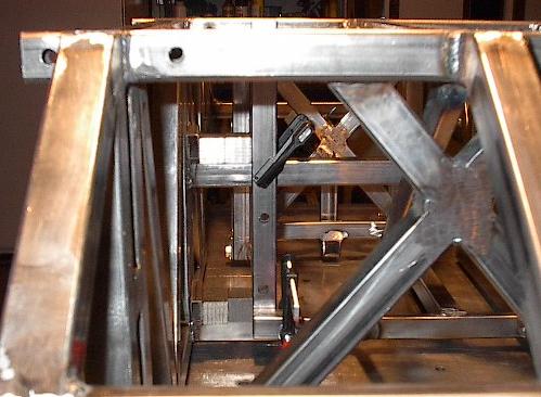
| This shot shows how the third battery is going to fit. I thought it was dreadfully difficult to get that aft battery into the chassis like this, but that was only before I had to get it out. I'm going to have to construct some kind of a handle onto the side of the battery that goes here otherwise it won't ever come out. It is remarkably hard to get a good grip on these things when they weigh this much and they're surrounded by all that structure. Anyway, almost everything seems to fit, and I'm just about ready to finish this chassis up. |
 |
| Here's the one spot that didn't fit so well. No big deal, just a little spur of steel that sticks out just a bit too far. I'll grind it down right now. |
 |
| Here it is all ground flat. That should improve the fit quite a bit. It won't make getting it in or out any easier, but that's a different issue. |
 |
| Here's the first of the three remaining pieces of steel. This will separate the two batteries in this compartment. The alignment of this member was one of the main reasons I did the battery fit check earlier -- I marked the position of this bar with the batteries in place. |
 |
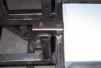
| Here's the second of the three pieces, and the first of the two that I drilled earlier. This should serve as a mounting point for the speed controller. Here I've clamped it to spacers to make sure the position is just right. |
 |
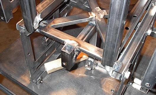
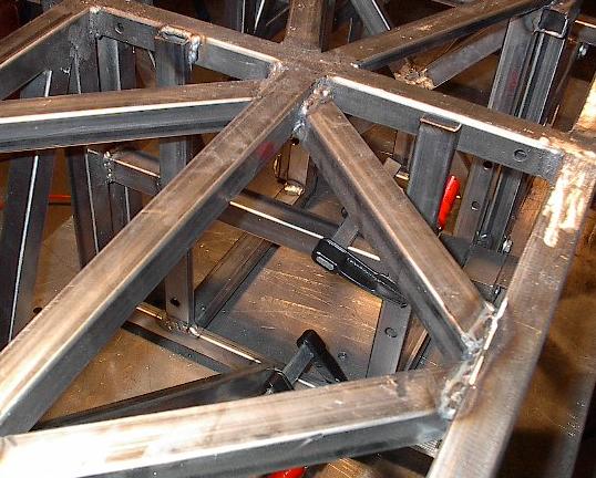
| And here's the last piece of steel clamped into place. It's very difficult to take pictures of some of these internal members, but I've done my best. Once this one is welded, I'll grind down the welds, clean up some rough edges, and the major structure will be done. |
 |
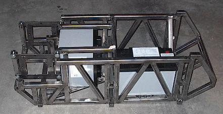
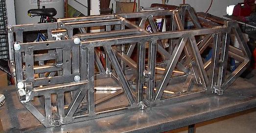
| There it is -- all of the major structure of the chassis. I've had my share of problems with it, but it looks pretty damn good. |
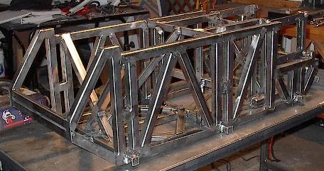 |
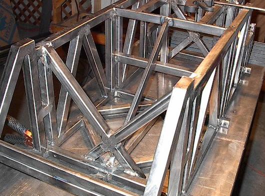
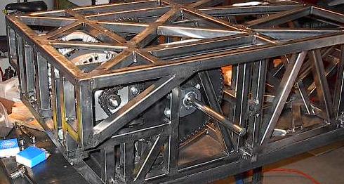
| The structure from a different angle. Here you can see that this is the plane which had the most eliminated members. I had to omit the back two diagonals in order to make the motors fit, and I replaced the middle cross to provide good mounting points for the speed controller. Despite this, I am not worried about the strength of the chassis. The center axle support has the lowest stress levels according to my finite element analysis, and the very back panel has a lot of structure already provided by both the chassis and the top panel. |
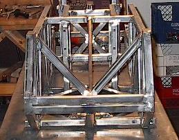 |
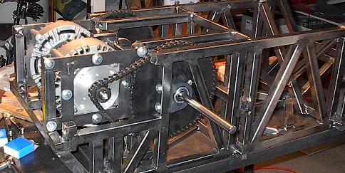
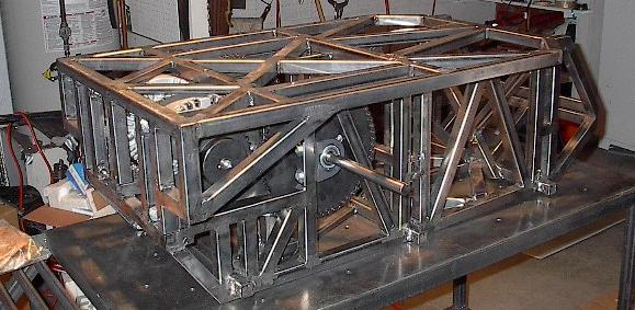
| One last picture of the same thing. Here you can see the back structure a lot better, including how the motor mounts bolt to the chassis. This is going to become important before I'm done today -- this area gets really tight, and there isn't hardly enough room for bolt heads in a lot of cases. |
 |
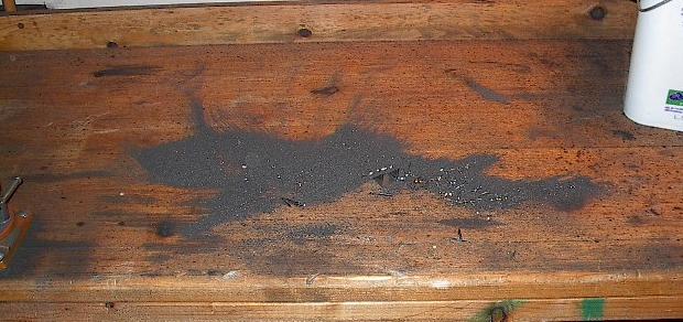
| Now that I'm dome with the major structure, I think I'll start working on the drive train. Before that, however, I'd better clean up shop. I can't exactly create a clean room, but I don't want to have this much grit laying around when I'm working with roller chain and motors and other things that I want to keep fairly clean. This is just some of the grit that had collected on my wooden work table over the past few days. I had a picture of the grit on the floor too, but the gray-on-gray didn't turn out. Suffice it to say that I swept up a lot of steel powder. |
 |
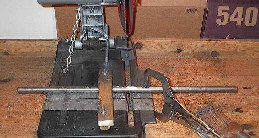
| The first step to assembling the drive train is to cut the drive axles. I paid over a dollar an inch for this thing, so it seems kind of a shame to cut it in half, but I need two drive axles. |
 |
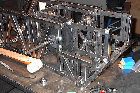
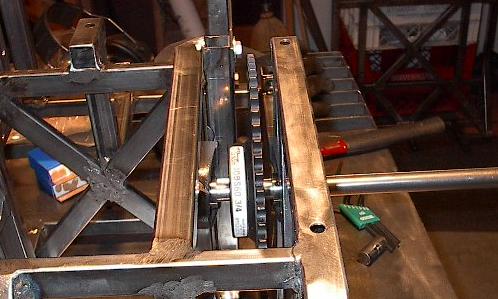
| Here I've mounted two bearings, one of the two drive axles, and the big, 60 tooth sprocket. This was a lot of work. I had a lot of trouble with the shaft keys fitting into the keyways. I think I'm just going to have to grind the keys down for the other sprockets. I thought they'd fit right out of the box, since this is exactly what they're designed for, but apparently not. Oh well, a lot of hammering and some creative clamping, and I've got the first sprocket mounted. Of course, note that the sprocket is covering some of the motor mounting bolts. I'm going to need to mount both motors before I do the other big sprocket. |
 |
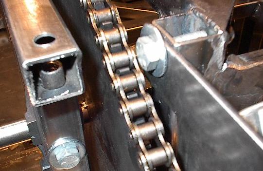
| These things are running in a very narrow channel. It looks like this one is lined up just fine, but we'll see that when I put the chain on it clips the bolt head seen here. |
 |
| Here I've mounted the motor for this side and fitted it with the small, 11 tooth sprocket. I ground this key, and it worked a lot better. Note that this is the motor that had all the fit problems -- it still fits too tight, but I think it's good enough. |
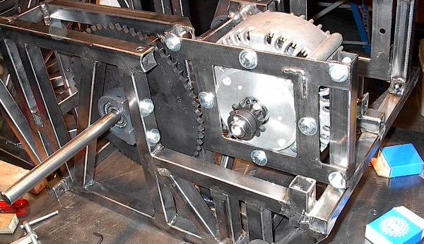 |
| Here I've added the chain to this side of the drive train. I've also mounted the other motor (we'll get back to that later). I've laid the chain length around the sprockets here, to figure out exactly where I need to cut the chain. |
 |
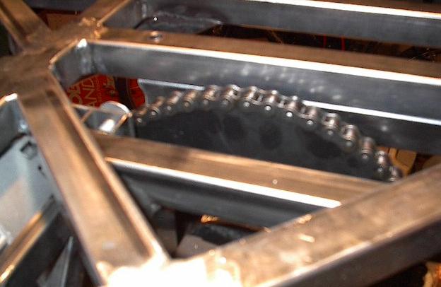
| And here's where I'm going to need to cut the chain. Notice a problem here? The tension is just about perfect, but it won't work like this. Roller chain is made of two kinds of links, which alternate along any length of chain. Here, the chain doesn't line up right. I'll have to cut it one pitch long in order to be able to splice it back together with my connecting links. Fortunately, I can buy offset connecting links which will link the chain back together just right. For now, I'll cut it long. It shouldn't be any problem to trim it later. |
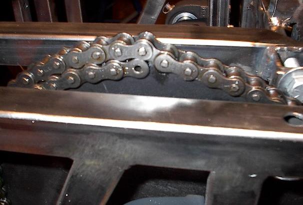 |
| Cutting roller chain is fairly simple, if you know its anatomy. Each joint consists of an axle, a shaft, and a bushing. The axle is riveted to the outer plates, the shaft is connected to the inner plates, and the bushing is free (that's why they call it roller chain -- the rollers ride along the sprocket to provide smooth power transmission). All I have to do is grind off the rivets and tap out the axle link. Here's the chain, with the rivets ground off. |
 |
| Here I've wrapped the cut chain around the sprockets, and linked it back together with one of my full connecting links. You can see how much slack this extra pitch length has created. This will look a lot better once I get my half-links. |
 |
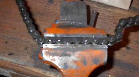
| Remember that bolt that I said was going to cause a problem? Here it is, causing the problem. The chain hits it. Not hard at all -- the rivets just barely tap the bolt. This, however, will be a big problem at speed. I can fix it by shifting each of the sprockets to the side. This will be quite a bit of work because of the tight fit of this sprocket, but I can do it. |
 |
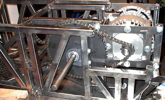
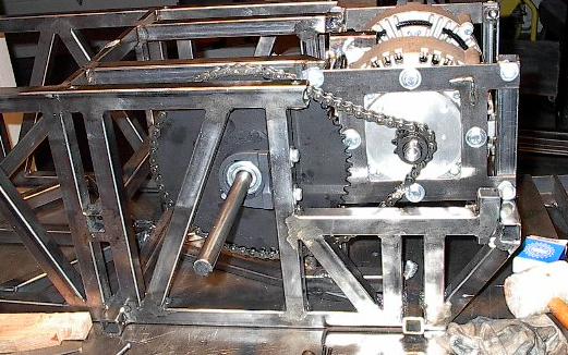
| Here's the same thing on the other side. I mounted the large sprocket, both bearings, and the motor sprocket. Then I cut the chain and spliced it back together. You can see again the slack in the chain. At slow speed, this wouldn't really be too much of a problem, but at the kind of power transmission I'm talking about, I can't tolerate it. |
 |
| Here it is with the top panel on, just to make sure everything fits. The back half of the chassis is really crowded, and the running drive train comes very close to structural members and even other components, so I have to constantly double check all of the fits for interferences. |
 |
| You can see here the main reason I will be bolting a Lexan plate to the top of the robot. The drive chain runs up and into the inch thickness of the top plate. This is less than half of an inch from the platform, and leaving it open is just asking for a lost finger or worse. |
 |
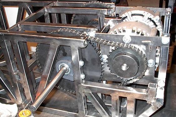
| Now that I have that part of the drive train set up, it's time to work out the other gear reduction. The first set up was a 60:11 reduction, which should give the robot a top speed of around 10 mph. Here, we're looking at a 2:1 reduction, kicking the speed up a notch to over 25 mph. I also had to cut a short length of chain to add in order to make it reach. For this setup, I won't need to use the half-link to get a good fit. You can see here a good chain tension. |
 |
| Well, I'm going to call it quits for today. I finished what I was supposed to be done with yesterday, so I'm only a day behind schedule. I'm planning on wiring things up on Thursday. I was going to test it for the first time then, but I won't be able to now that I'm down to two batteries. |
 |