| Today I started off with the motor fit problem from yesterday. I'm trying to figure out exactly what the problem is. The back member seems to be a little too far in, but I can't imagine how that could have happened -- I aligned it when I first made the mounts, bolted them together, and there should have been no way for it to shift. |
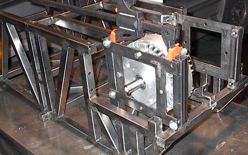 |
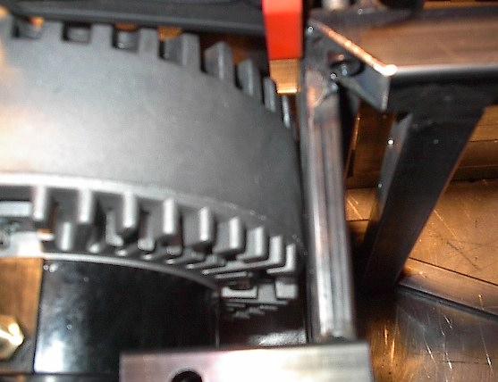
| I spent some time grinding and hammering, played with the fit, and I think I finally see the problem. The motor isn't actually perfectly cylindrical -- the sides have a very slight barrel shape. This means that I aligned the mounts to the motor's diameter at the front, where it was slightly narrower than its widest point. This is causing the middle to jam against the "X" shaped structure that I added after welding in the motor mounts. |
 |
| Now that I know what the problem was, I was able to work on it a bit. I hammered on the members that were in the way, bending them out slightly. I then ground down whatever I could get at in hopes of making a little more room. I've finally got the motor to fit, but it's really tight. I'm a little uncomfortable cramming such expensive motors into such a tight spot, but there's nothing for it at this point. They're supposed to be rugged motors, so I guess I'll just push on. |
 |
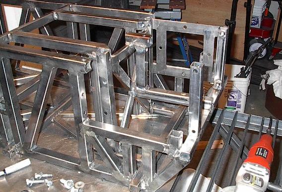
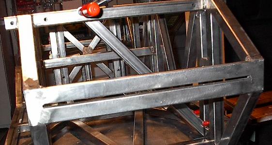
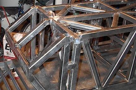
| Here's the problem spot without the motor mount bolted in. If I add the two members I mentioned earlier to the very back of the chassis, the motors will no longer fit. There just isn't any good way to resolve this problem, and the members are welded in too good to get out without some serious destructive grinding. If the members fail due to the lack of support from the missing two members, I know exactly how I can reweld them to make everything work out better. If not, I have nothing to worry about. Moving along. |
 |
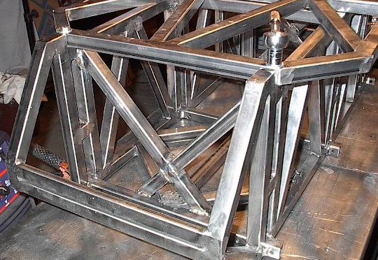
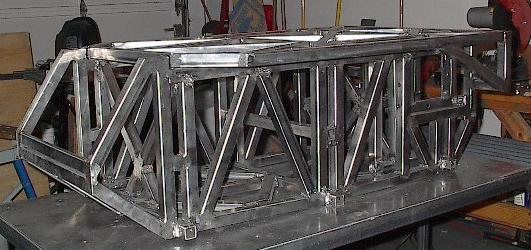
| Here I've bolted the top panel on using all ten mounting points. Everything still lines up just fine. Time to start adding the final structural elements to the front half of the chassis. |
 |
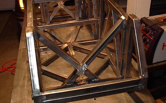
| Here's the first cross member for the front half. This will divide the computer compartment from the front batteries, while leaving room for the suspension travel. Lines up pretty good. |
 |
| Here I've added two more members to form the cross shape that most of the cross-members take. This one looks great. |
 |
| I welded some more, removed the top panel, welded again, and ground the welds flat. Here's the finished cross support. |
 |
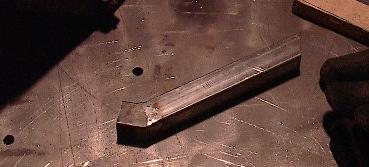
| Back to basics here. This is the first time I've used the flat table top to arrange pieces in quite some time. Here I'm welding two angled members together to form a corner shaped piece that will form a kind of skid plate for the chassis, so when it bottoms out the computer enclosure won't be damaged. |
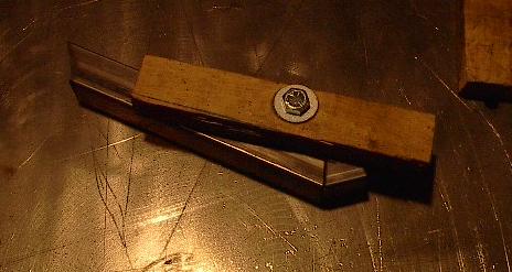 |
| Here it is welded and ground. This should be the same shape as the bottom foreword angles of the side panels with a little spacer to get everything to work out right. |
 |
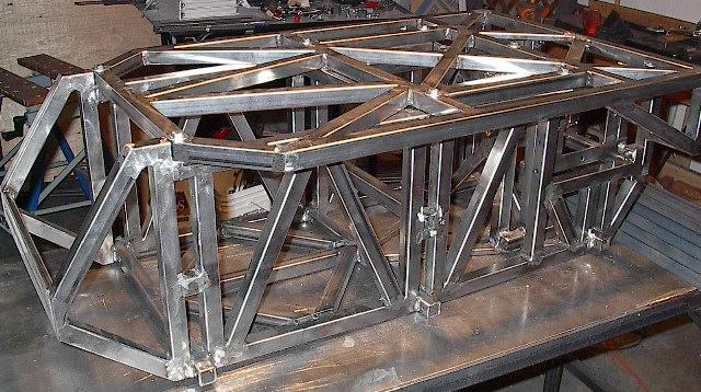
| Here it is installed. Looks great, but I think I'm going to call it quits here. |
 |
| It has been a short build day, and as of midnight tonight I'm officially behind schedule, but this is it for this day. Before I can be done with the major structure (which I was scheduled to be done with tomorrow), I have to make and install four more members and do a little more tweaking around the edges. I should be able to finish that on Tuesday. I'm not thrilled, but it isn't too bad -- nothing that will effect the overall project schedule too much. |
 |