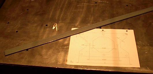
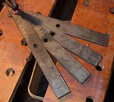
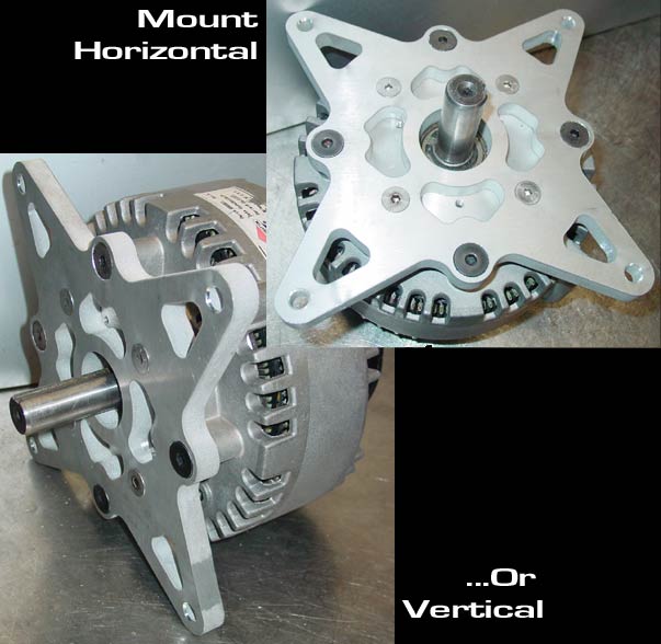
| I've been thinking a lot about how I was going to get started today. The next few members have to be aligned just right, and with respect to things that aren't even there yet. I just didn't trust my tape-measure skills enough to pull it off, so I'm taking a little detour. I'll get started by making the motor mounts, and then the members they'll bolt to. Then I'll bolt them to the mounts, and weld the entire assembly into the chassis. This way, everything should line up with the mounts and the motors just right. This picture shows a steel bar (1.25 x 0.125) and a picture of the motor mount. Sadly, the picture is not 1:1, so I'll actually have to do some measuring. |
 |
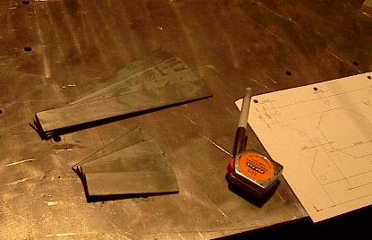
| Here that bar is cut into eight pieces. These will make up the structure of the mounts. If they prove too flimsy, I'll reinforce them with triangular supports, but that probably won't be necessary. |
 |
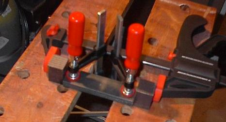
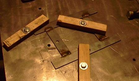
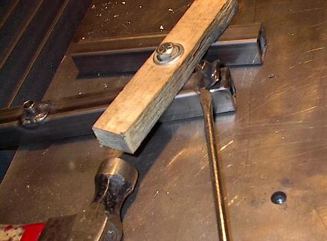
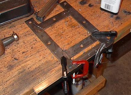
| More and more of my work lately is figuring out how to clamp something into place. Here I'm clamping down the bars to be drilled, but you'll see a lot of creative clamping action later on today when the chassis starts to get crowded. |
 |
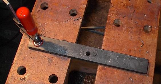
| Here's a picture of more bars with a hole (yes, it's supposed to be off-center). These should line up with the tapped mounting holes on the Etek electric motors. |
 |
| Looks like stacking them worked out just fine. I'm always nervous when I do something like this -- if I'd accidentally drilled through at an angle the bottom pieces would be off. This time it looks like everything went just fine. |
 |
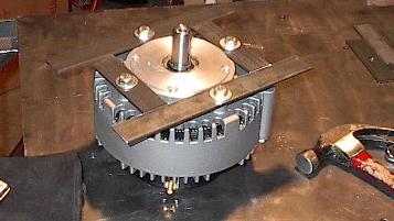
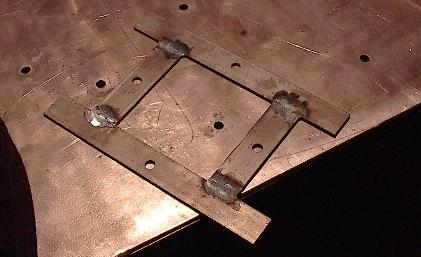
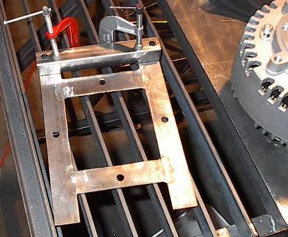
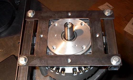
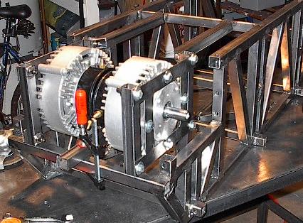
| Here are four of the bars bolted onto one of the motors. This took a bit of tweaking to get right -- I ground the edges of the bars to get them to nest onto the inner ring of the motor just right. I figure that if I get everything lined up directly on the motors, I can't go wrong. |
 |
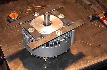
| Here they are with a few quick welds. Everything still lines up just fine. These welds are just the start, though. These mounts are very critical pieces, and will be subject to significant loading during normal use. These seams are going to have to be good and strong. |
 |
| Here I have the mount clamped to the table. I'm going to go back over these welds with really hot, wide beads to melt everything together really good. Then I'll grind them down and do the other side. That should make the strongest joints I know how to weld. |
 |
| Here it is ground down. Note how much mill scale there are on these bars. I'm going to brush these down once they're all welded together to take care of this. |
 |
| Here's the other side welded up. I got these welds really hot to melt the bars together all the way through. You can see how big and spread out the welds are because of this. |
 |
| Here's a motor mount that has been half brushed with a carbon steel cup brush wheel. It made a huge difference. Now they look like nice steel plates instead of dirty slag bars. |
 |
| There they are -- two Etek mounts, custom made from scratch. Sure, they aren't the most precise, beefy, or pretty mounts I've ever seen, but they'll work just fine for my purposes. |
 |
| Now I've just got to align the motor mounts with the chassis members that they'll bolt to. Lucky for me, I haven't welded them to the chassis yet, so this is pretty easy. Once all the holes are drilled and everything is aligned just how I want it, I'll weld the whole assembly in. It sounds pretty fool proof, but every time I say that I screw it up. |
 |
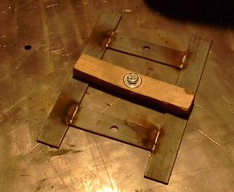
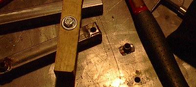
| Here's one finished up. Or, so I thought. One of those weld nuts isn't supposed to be there. The bolt is going to pass through the mount, member, and then half of another member before getting to the weld nut. Oh well. A build day without me doing something stupid just wouldn't feel right. |
 |
| It turns out that if a welder were a function, its inverse would be a screw driver, a hammer, and a lot of noise. Mission accomplished. |
 |
| It aint pretty, but it worked. This part will be welded to another chassis member anyway, so it doesn't matter. In fact, it will be welded to another member I screwed up that is even uglier, but we'll get to that later. |
 |
| One final check to make sure that the first mount still fits. Looks great. As I type I know that this very same mount is sitting out there in the garage fitting nowhere near this good, but at the time of this picture everything was going my way. |
 |
| Time to mount up the second motor mount. It's surprisingly hard to clamp this particular angle just right for drilling, but I managed to work something out. |
 |
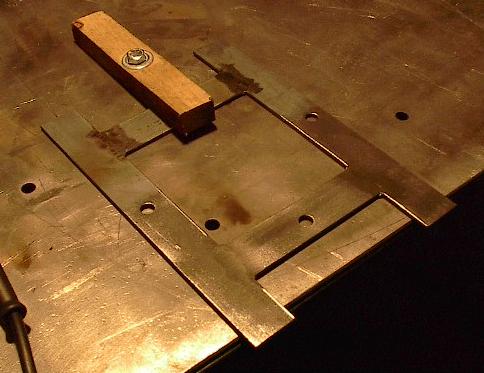
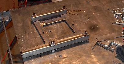
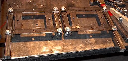
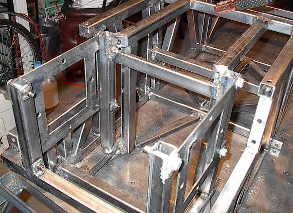
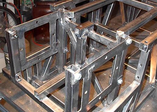
| Here are both motor mounts and their relevant chassis members. I'm going to weld these into the chassis assembled (which, of course, causes problems. But then again, what doesn't?) |
 |
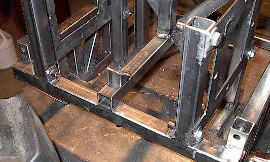
| Remember that ugly spot where I had to break off the weld nut? The one that I wasn't worried about because it was going to get welded onto an even uglier part? Well, here's the even uglier part. The motor mount bolts need to go through one wall of these tubes (which is why they're cut at angles), but I didn't drill them before installing them. Now that they're in, there isn't enough room to get my drill in there. So, instead of a hole, I've cut slots in them with the grinder. I'll weld the crap out of this whole thing, and it should be fine. |
 |
| Time to weld these suckers in. There's a lot of things that need to line up, so I'm going about this in a fairly methodical way. I'm lining up everything with the motors, and then checking everything for square, double checking side distances, clamping all the aligned members, and making a single weld. Then I do it all again, just in case anything warps on the first weld. |
 |
| I've also got to double check all the fits with the top panel on. This is to make sure that there aren't any unexpected collisions and that all of the as-of-yet unconstrained mounting points still line up. The motors actually protrude into the plane of the top panel by a half of an inch. |
 |
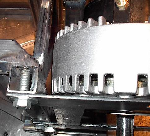
| You can see that here. This is why I used those two 1 x 0.5 inch tubes in the top panel construction. They're shown here, running right over the motors. Looks like they line up just right. |
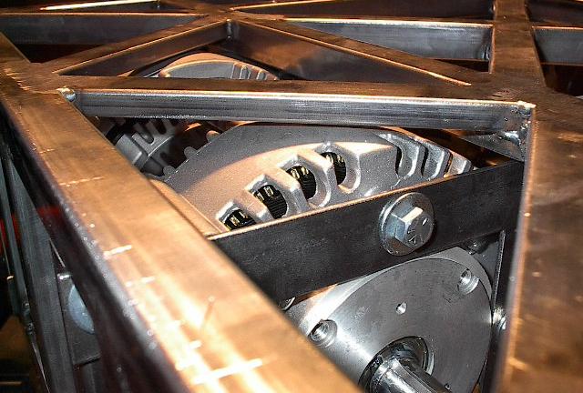 |
| The roller chain drive train is going to run down this narrow gap. This should make sure that everything is really sturdy and also saves space. I'm a little hesitant about how close the running chain is going to come to some of the chassis members, but it shouldn't be a problem if my calculations are correct. |
 |
| It's a good thing I've got good heavy batteries, otherwise this structure might end up a bit back-heavy. |
 |
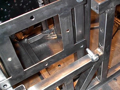
| Remember when I said installing it assembled caused a problem? Well, here it is. That bolt is too long to get into or out of the hole (well, I did manage to get it out, but it was a huge pain). I didn't realize that this gap was going to be so tight, so some of the bolts are causing trouble. I tweaked a few hole fits and tolerances and I think I have it so I can work through it, but it's always going to be kind of a pain. |
 |
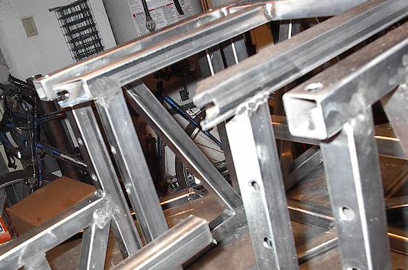
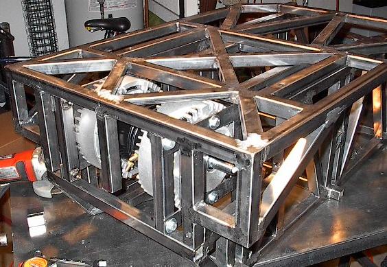
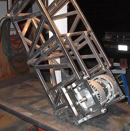
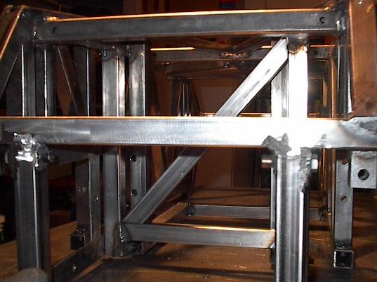
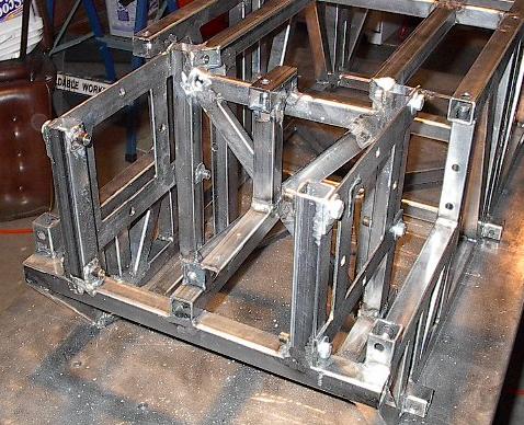
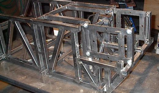
| Here's the aft portion of the robot with the motor mounts and supporting members welded in. You can see where the two ugly parts come together in lots and lots of weld, and everything turns out OK. Things look pretty good. |
 |
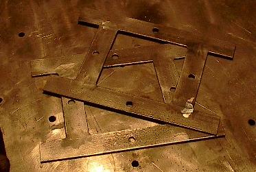
| It occurred to me that because of the way I made these mounts, they aren't interchangeable or even reversible. I welded these angles onto each mount to mark them -- they should uniquely identify the mounts while indicating their proper orientation. |
 |
| Now that that's all taken care of, it's time to get back into the swing of things. Cut, shape, weld, grind. This member is one of four that will separate the motors from the battery compartment, supporting both. |
 |
| Here's another of the four members. This is actually the first angle I've gotten to in this dimension, but there will be quite a few more. Also, because of the way I've been manufacturing the supporting members in the aft portion of the chassis, I was unable to make any templates for these. I just had to eyeball this one and tweak it until it fit. It went pretty well. |
 |
| Here I've added the last two of the four members. Again, I had to eyeball these, but they came out looking just fine. I'm not sure, but I think that the one on the upper left is slightly out of plane -- after I added this structure, the left motor ceased to fit (we'll get to that later). |
 |
| Here I'm aligning another member. This one will support the backs of the motors, so it had to be lined up with a motor mounted. One end welds to the very back member as you can see. The other terminates right in the middle of the "X" shaped structure I just finished creating. |
 |
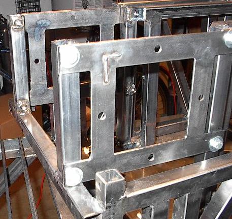
| Here I've added two new members. I welded these into place, bolted the top plane on, and then drilled a hole all the way through the top panel and the little block on top seen here. There's a weld nut mounted in the juncture of the two new members, making this the ninth bolt connecting the top panel to the chassis structure. There will be ten when I'm all done. |
 |
| Speaking of that tenth mounting point, this is destined to be it. This little thing will be drilled in the same way as the previous one -- with the top panel attached. This is a good way to ensure that everything lines up when all is said and done. |
 |
| And here it is drilled. That brings me very close to having the aft portion of the chassis completely finished. I still have to add two more members, which will form a "V" shaped structure here in the very back. With that, everything will be in place and I can start finishing the foreword portion of the chassis. |
 |
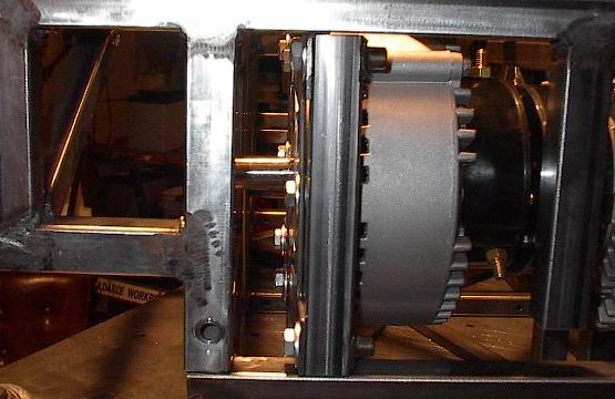
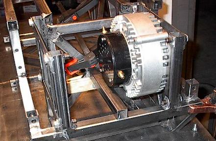
| Unfortunately, there's a problem. This motor used to fit here, now it doesn't. At first I thought I'd mounted the "X" shaped structure slightly out of plane, but I'm starting to think that maybe the right motor mount support is the one that's off. I have no idea how this could have happened, but it seems to have. It's really late, though, so I won't be able to tackle this tonight. First thing tomorrow I'm going to take the mount off this side and go after the support with a grinder. Hopefully that will yield some results. |
 |
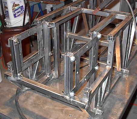
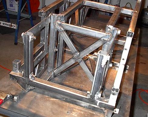
| A picture of the day's progress. It looks good, it even measures just fine as accurate as my tape measure can tell, but the left motor doesn't fit. I think I can get it fixed in fairly short order with a little grinding and maybe a little filing in the bolt holes. Then I just have to cut, shape, and weld the two back panel members, and the back half major structure will be done. Then I finish the front half, and get to work on component mounting and supporting. |
 |