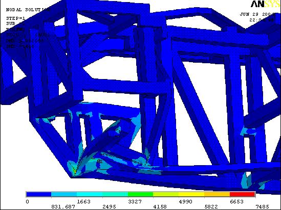
| This is the stress distribution for the first load case. This was a normal loading case, where double the recommended payload is carried by three of the six wheels. We can see here a maximum stress of only around 7.5 ksi. No problem. |
 |
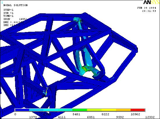
| Of course, loads aren't always going to be evenly distributed between the axles. The next three load cases are for focused loads. This one is the case where double the suggested maximum payload is completely supported by one of the front wheels. We're talking about half a ton of load on a single wheel. Max stress: 12.3 ksi. No sweat. I'll get worried when it hits 18 ksi (safety factor of 2 on the yield of steel. |
 |
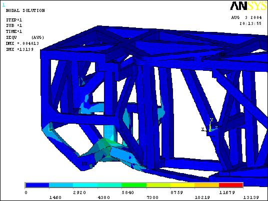
| This is the same idea for one of the middle axle wheels. Here we see a problem: almost 20 ksi. A-36 structural steel will yield at 36 ksi. However, if you zoom in on the stress concentration for this load case, it isn't at the axle mounting location. It's at the top, where the platform connects to the chassis. Here, I added a small chamfer to eliminate a "divide by zero" error created by ANSYS naive Gaussian elimination matrix operation. This chamfer created a shear plane in the model that simply won't exist in reality. The highest stresses at the axle mounts are around 10-11 ksi, which should be no problem. |
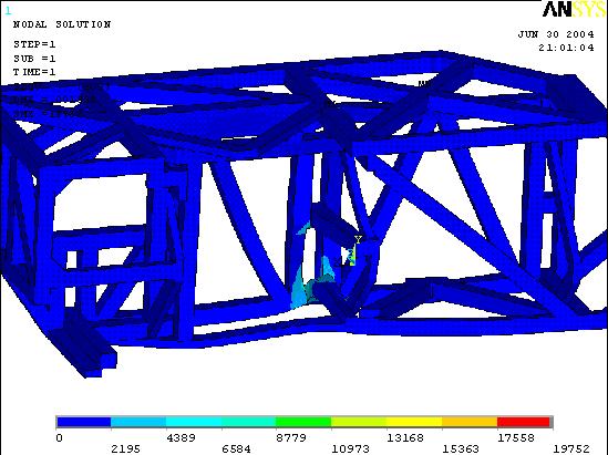 |
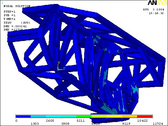
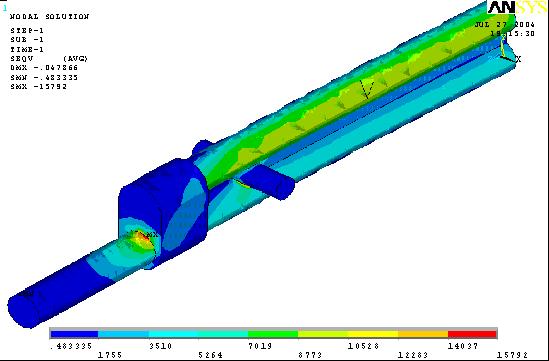
| This load case is the same thing for the back axle. This generated the highest real stress in the finite element analysis. What you see here is the reinforced structure, with a stress that was reduced to just over 13 ksi. Before the addition of that small member, it was over 20. |
 |
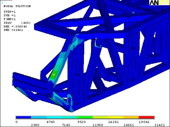
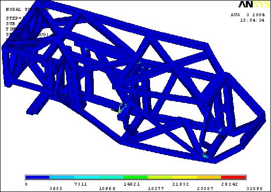
| This load case represents a loading on the front axle. This loading produced high stresses due to stress concentrations in the very front members. These stress concentrations will not be a problem in the final design because the 3/4 inch axle will support a great deal of the strain. In order to represent this, I grounded the front members and loaded the aft evenly. The 21.4 ksi load shown here occurs at the same location as the maximum stress in load case 3, and for the same reasons. The actual stresses of concern can be seen here to be no more than around 15 ksi. High, but I still have a safety factor of more than two. |
 |
| This load case is a side load. This isn't expected to happen very often, but the structure still needs to have a certain amount of lateral stability. Even under 600 pounds of load, the stresses stay under 12 ksi. |
 |
| This load case is the chassis subjected to a positive bending moment over its entire length. This means that the fore and aft axles are supporting the weight while the payload is focused over the center. This load case showed another serious stress concentration, but this one is at a new location. It also, however, is an artifact of the software. There are five different members coming together at slightly different angles. This creates several very small surface elements, which were then transferred into shell elements during the meshing process. I am confidant that this will not manifest itself in reality. |
 |
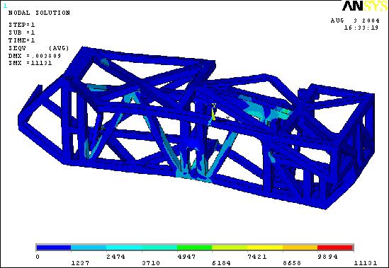
| This load case is the chassis subjected to a negative bending moment. This means that the weight at the fore and aft portions of the chassis are supported by the center axles. This is something I expect to happen a lot, because the center axle is half an inch lower than the other two. The stresses found here were just over 11 ksi, which is very acceptable. |
 |
| The final bit of analysis is on the axles. As we can see here, the rounded I-beam design workes exactly as desired. Almost all of the material supports a significant amount of load, and the result of the high area-moment of inertia about the neutral axis is a good ability to support bending moments. Perfect. |
 |