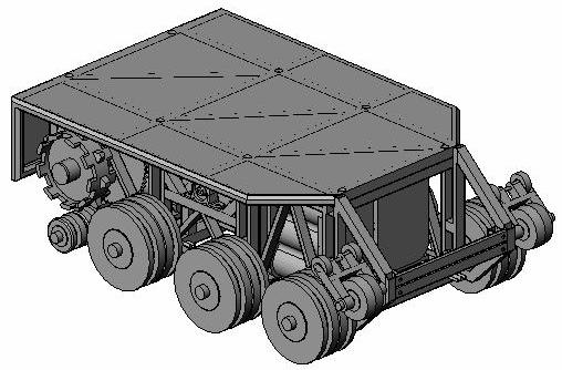
| This is a picture of the first fully-developed solid model that I did using SolidWorks. This design used the smaller batteries from before I realized their limitations. At this point in time, there are a number of design choices that I have since changed. You can see here the double-wheel design, which I threw out when it became apparent how much the wheel modifications necessary to make this work would compromise their strength. This design also has a metal platform, which I have replaced with a transparent polycarbonate one. Also note no finalized positions for electronics or computer systems. At this point in time, I wasn't even planning to have a heat exchanger. |
 |
| To get a better view of how everything fits together, we'll start from the inside out. Here, we can see the axles and how they must pass through the structure. This was where I began designing, so I figured it was a good place to begin seeing how the solid model cametogether. |
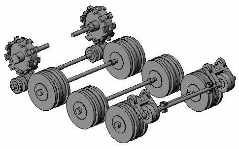 |
| Then, around the axles, we add the major components. Here is how the motors and batteries were planned to fit around everything. Not the cylindrical-cell batteries pictured here. These are Optima Spiral-cell batteries, which were what I was going to do. They have great vibrational stability and ability to source a whole lot of current, but their energy density just isn't high enough. |
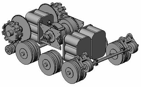 |
| And, of course, we need some kind of chassis to hold everything together. This is the solid model mentioned in the sketches section. This shows a structure that will hold everything together and shows a lot of promise. Unfortunately, the batteries used here just won't cut it. |
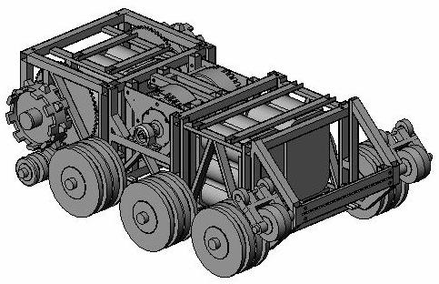 |
| Here's a picture of just the chassis. You can see where each of the components fits in and how they are mounted together. Note in particular all of the open space around the motors. This was necessary to keep the axle spacing, but it was just wasted space. This is what I was able to optimize when I added the bigger batteries. |
 |
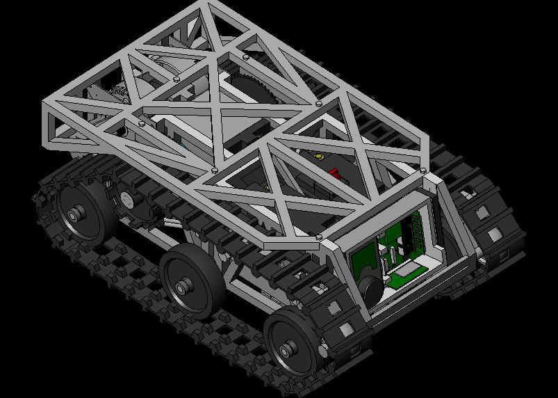
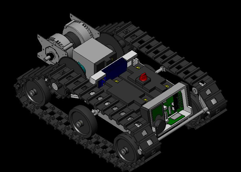
| After a few iterations, and even some solid modeling not shown here, this is the design I came up with to house the larger batteries. Note that in this design a much greater range of requirements are taken into account, including the track, electronics, computer system, and heat exchanger. Also, as we'll see in the next pictures, the motors have been moved to very aft of the robot. |
 |
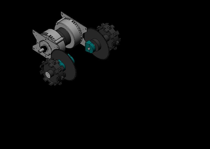
| Here is a picture of the motors, sprockets, and drive axles. By moving the motors to this position, I was able to eliminate a great deal of wasted space. Even though I nearly doubled the battery capacity, the overall length of the robot only changed by about an inch, while I was actually able to decrease the width by a token amount. |
 |
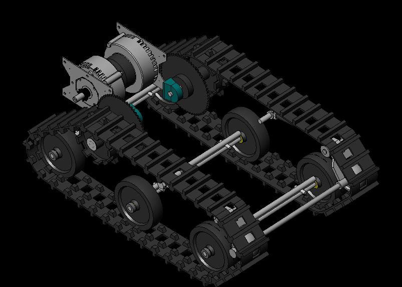
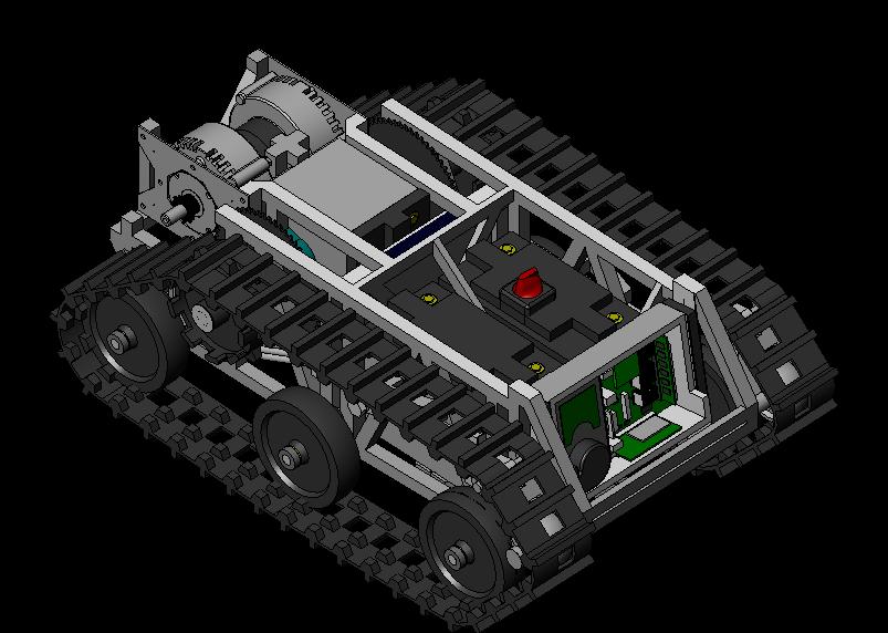
| Here we add the axles, wheels, and track to the assembly. This constrains the chassis and structure and determines the locations of the other components. |
 |
| Speaking of other components, here they are. 200 pounds of batteries, a speed controller, the computer system, and the heat exchanger. All with room for axle travel and the structure that will be added in a minute. |
 |
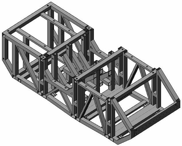
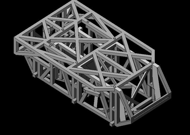
| So, to hold the whole thing together, we need a chassis. This structure seamlessly integrates all of the design constraints. It supports all of the components and should provide enough structural support to withstand quite a bit of abuse. We'll see exactly how much after the finite element analysis. |
 |
| Here's a picture of the chassis and additional structure elements. This is the design that I will be importing into ANSYS for finite element analysis to determine deflection under load and stress distributions. |
 |