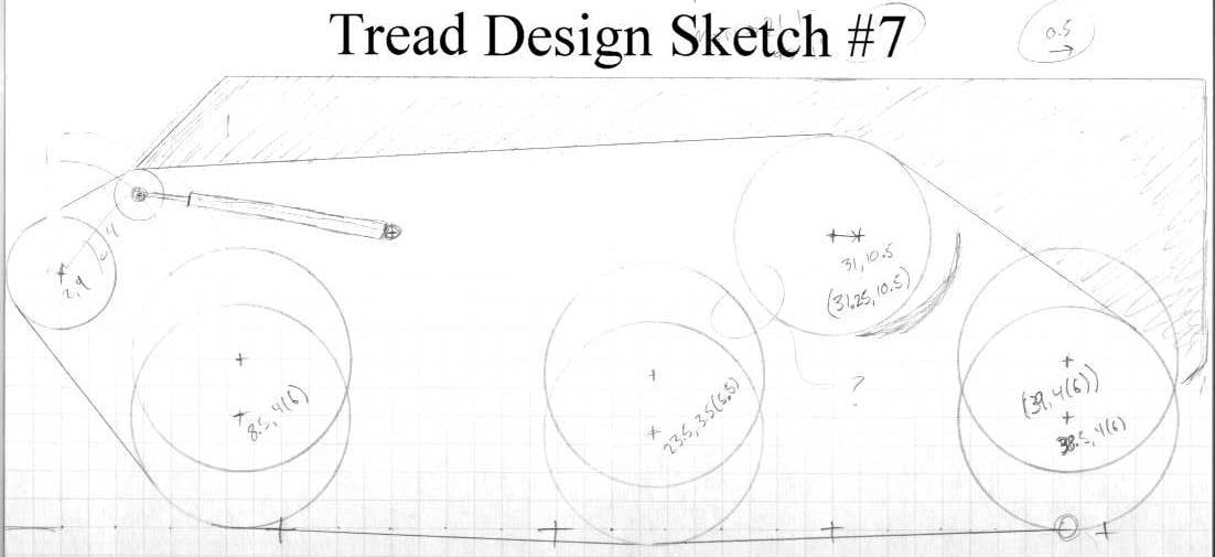
| An easy place to begin the design, way back over a year ago now, was with the track layout. This was a major constraint on the layout of everything else, because the chassis has to accommodate all of the axles with travel, and still leave room for the components. This sketch shows one of my first developed iterations of track layout. It is still largely based on a Model S90-A Japanese Ground Self-Defense Force Battle Tank, which I picked for a spring point. |
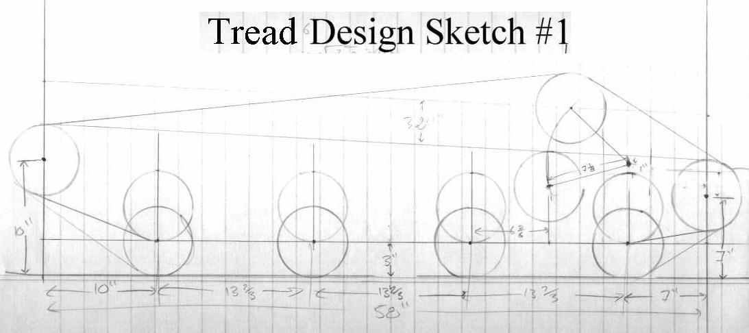 |
| The initial sketch revealed a major problem -- if I want a given amount of suspension travel, my wheel radius must be at least this much. That wasn't the case in the previous attempt, so that was the big change here. This design uses big 14" wheels. I believe at this point I was considering junk-yarding the wheels. I figured I could get cheap car or trailer rims and fill them with some machineable plastic or something. |
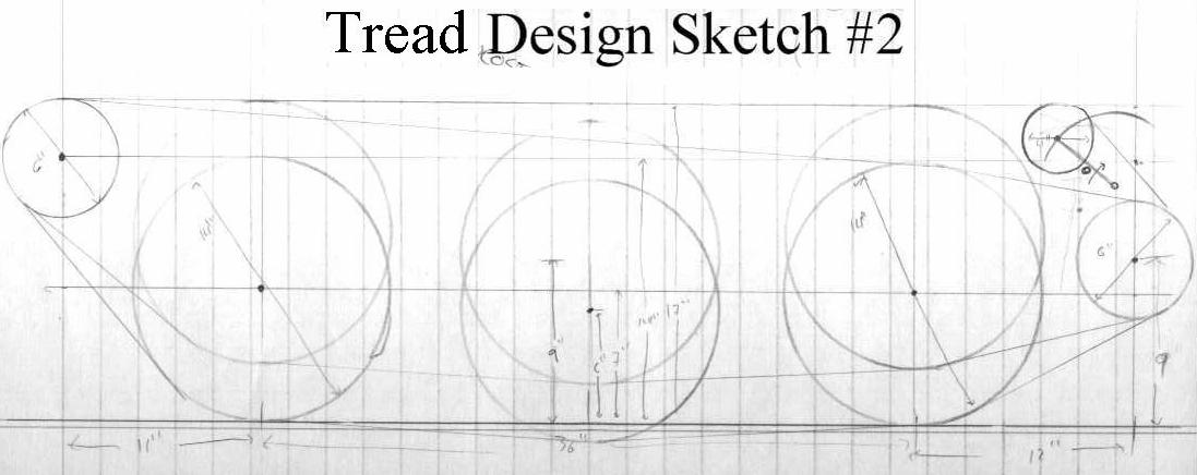 |
| Here I'm starting to realize just how much of a pain in the ass my tensioner assembly is going to be. I need to find some way to mount springs or other mode of input force, and keep the tread tension resultant along a good angle. All of this as to be accomplished without interfering with the travel of any of the other wheels, and with as few moving parts as possible (bushings and bearings can get expensive fast). |
 |
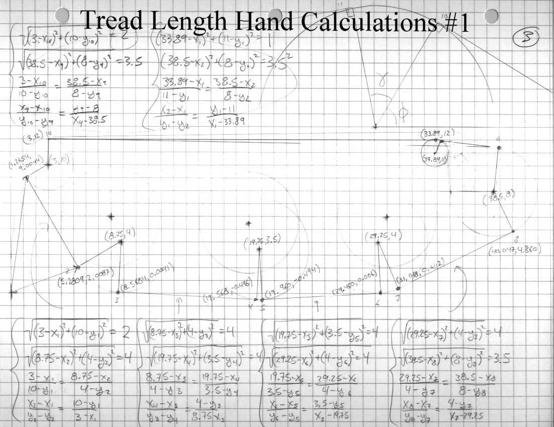
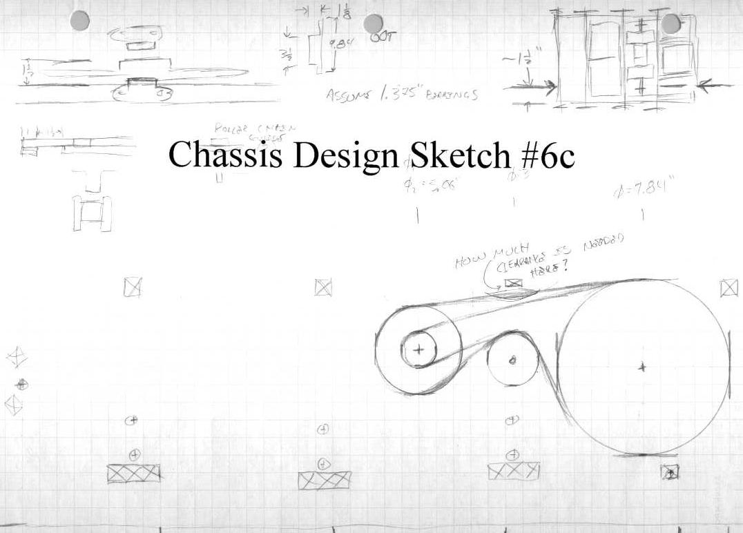
| Here I have the first layout that I am reasonably happy with, and it's time to start figuring out just how must slack the tensioner is going to have to take up. This was a surprisingly difficult problem. I need the total track length for extended and compressed suspension. I did this by hand for maybe three iterations before getting fed up with it and creating a driven equation in SolidWorks to do the work for me. |
 |
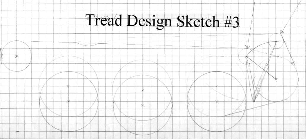
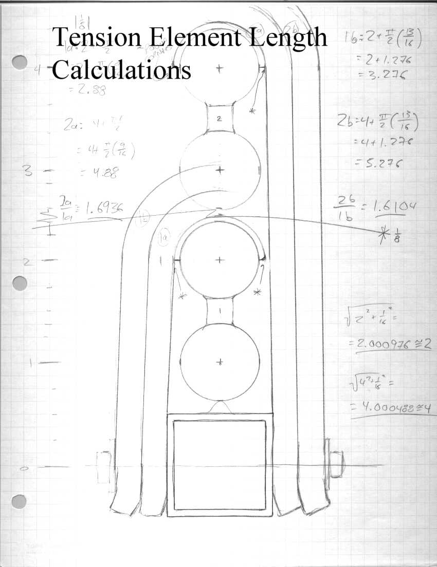
| Here are two more sketches used in the hand calculation of tread length. There are more, but they aren't very entertaining. Just believe me when I say it wasn't a walk in the park. |
 |
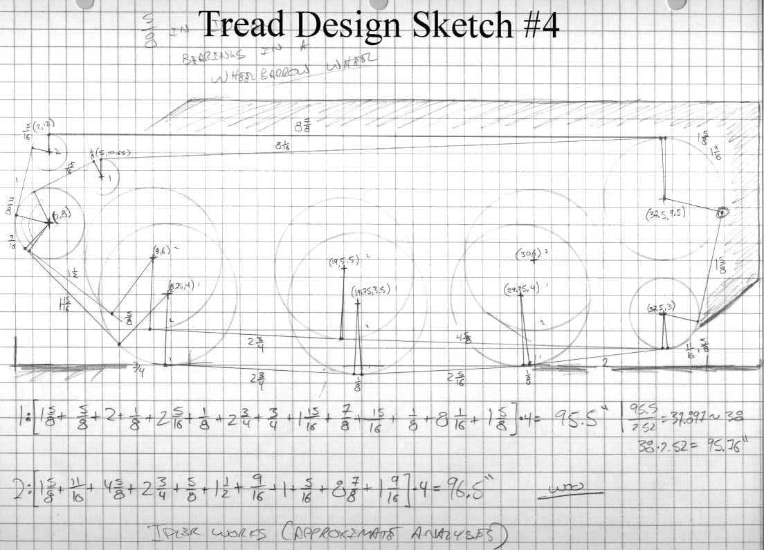
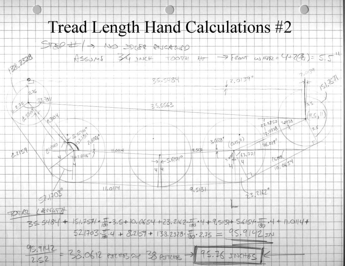
| The last picture of tread length calculations. After a half-dozen or so pages of this stuff and I was ready to let some software do this work for me. |
 |
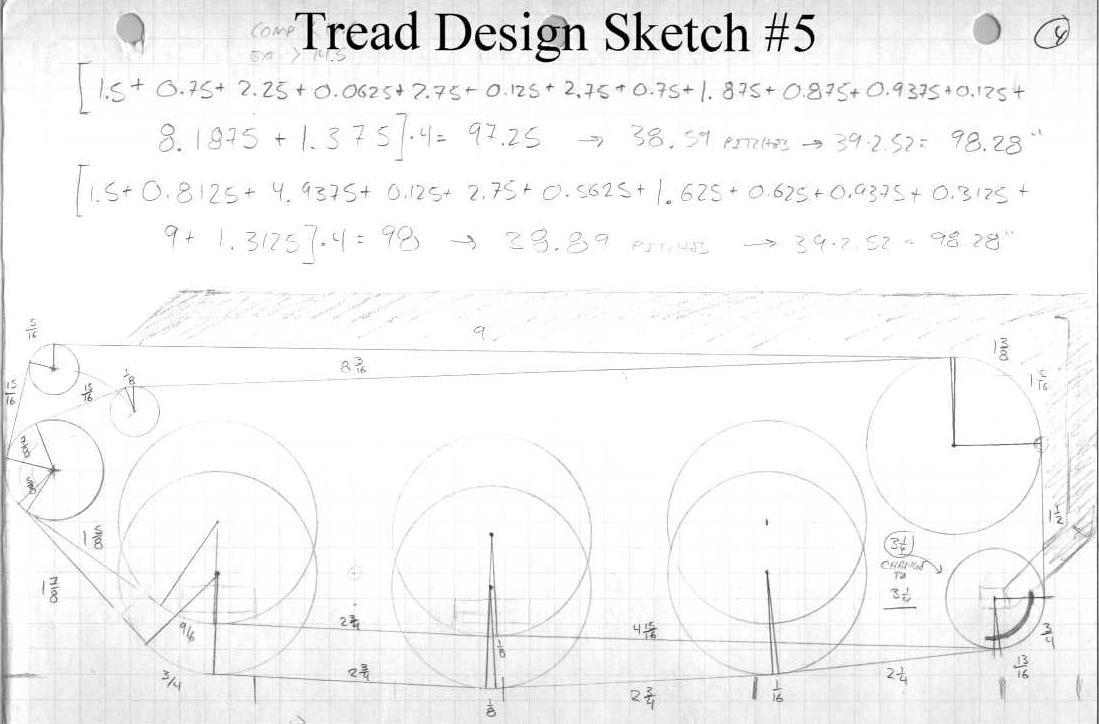
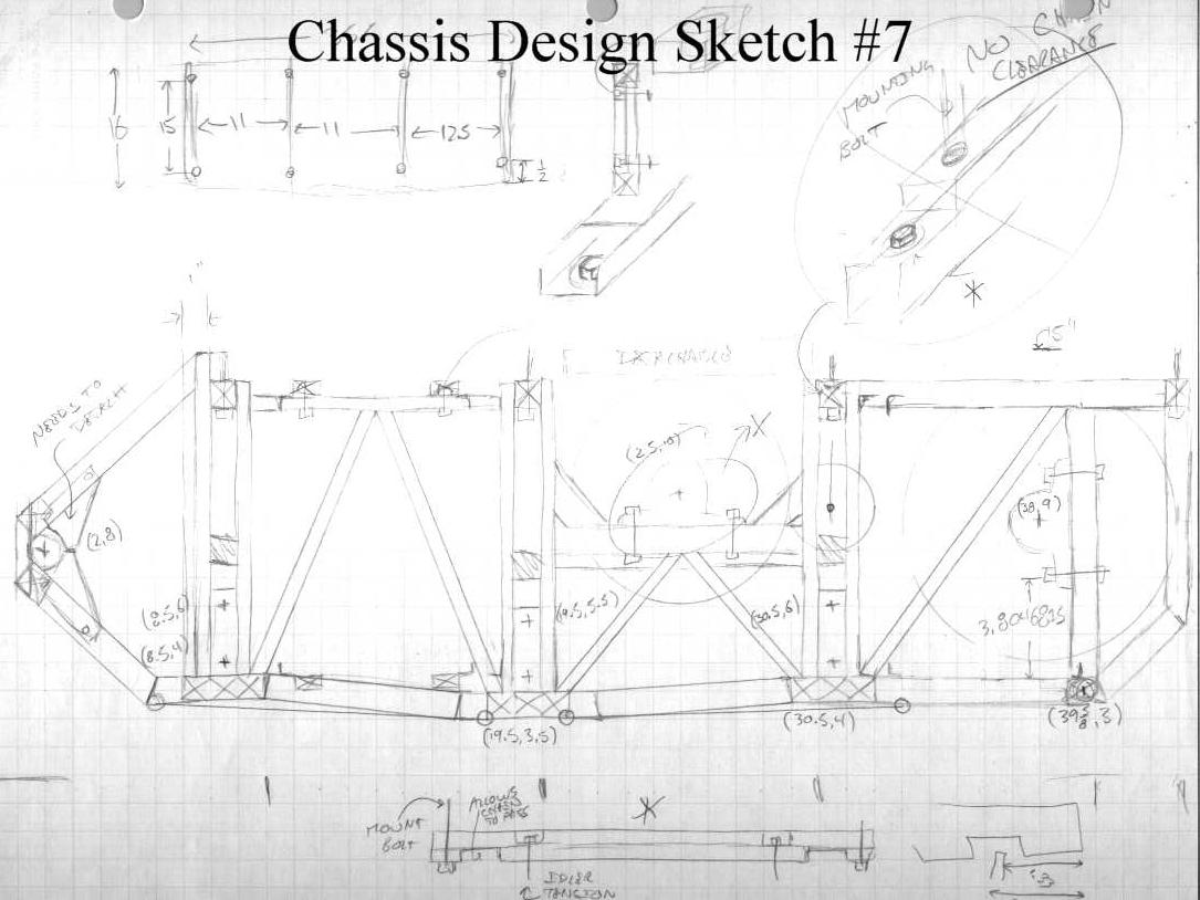
| I was starting to feel like I had a good design, and I started fine tuning. This sketch shows some slightly different axle positions and represents what I thought, at the time, was going to be my final design. This layout, if I recall correctly, went on to be one of my first that I took the time to solid model. Unfortunately, the design needed some more modifications before I could call it quits. |
 |
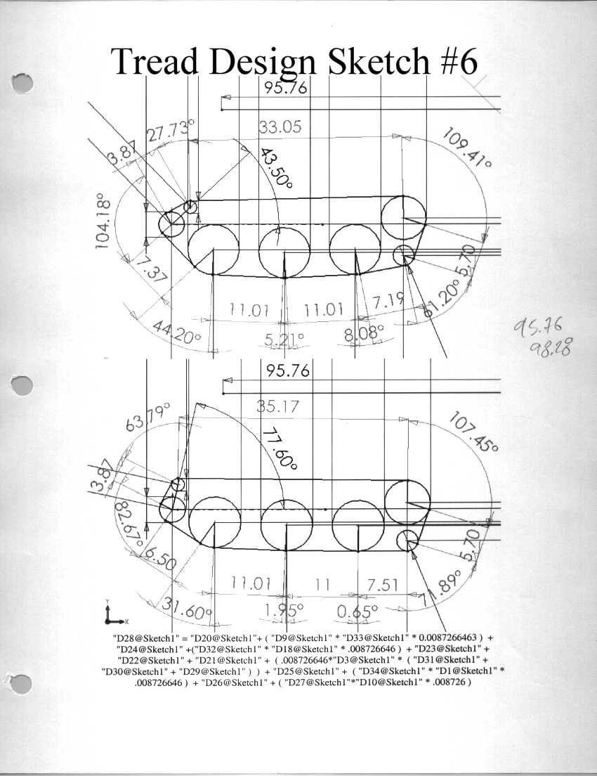
| Here is the track length calculation done is SolidWorks. Thank goodness for software. This saved me a ton of time in the long run and let me tweak the tensioner travel parameters to get them just right. |
 |
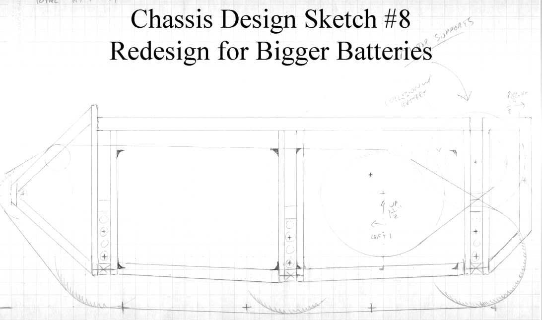
| The reason that this looks like a giant step backwards in terms of refinement of design is that it is. This was the point in the design where I realized a major problem in battery capacity. I had to pick new batteries of nearly double the amp-hour rating, and they were considerably larger. In order to accommodate this size, it was back to the drawing board. |
 |
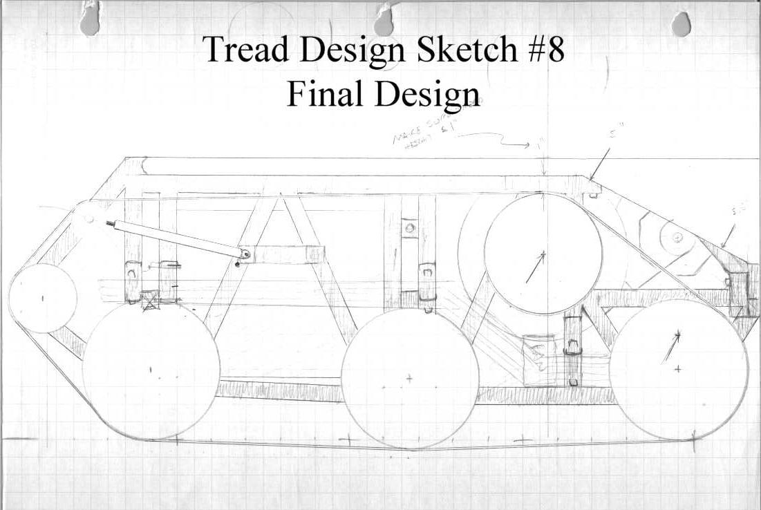
| With all of the experience of designing the previous "final" design, I was able to work through to a refined design again fairly quickly. Pictured here is a sketch that is very similar to what I will be implementing, including how it will interact with the underlying structure. |
 |
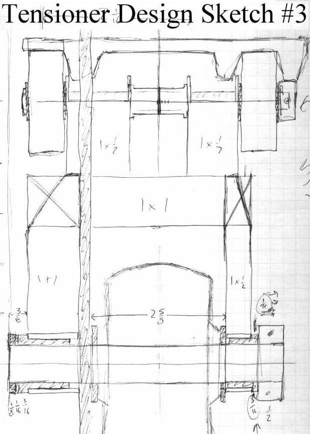
| Now that I knew what the tensioner assembly had to be able to do, it was a simple matter of three or four iterations to this design. This is a fairly simple little system which should minimize the amount of stress in the system due to input force while still delivering sufficient performance to keep the track on the robot. |
 |
| Of course, the reason that a tensioner is even needed is the suspension. I put a lot of thought into how I was going to accomplish two inches of travel for each of the six wheels, and have settled on using these tension suspension elements. However, in order to apply the experimental properties of this material that I determined in the lab, I had to know just how much they were going to stretch. With this, I was able to figure out exactly how much pre-load to put on the elements in order to achieve optimum control. |
 |
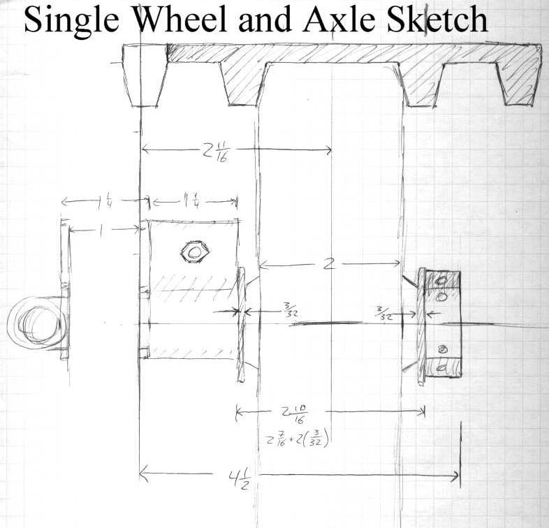
| Here is a sketch determining how to align the axle assembly with the wheels in order to run the tread exactly where I want it. My tread won't quite accommodate the width of the wheels, but it shouldn't be too hard to modify things to mate up pretty good. |
 |
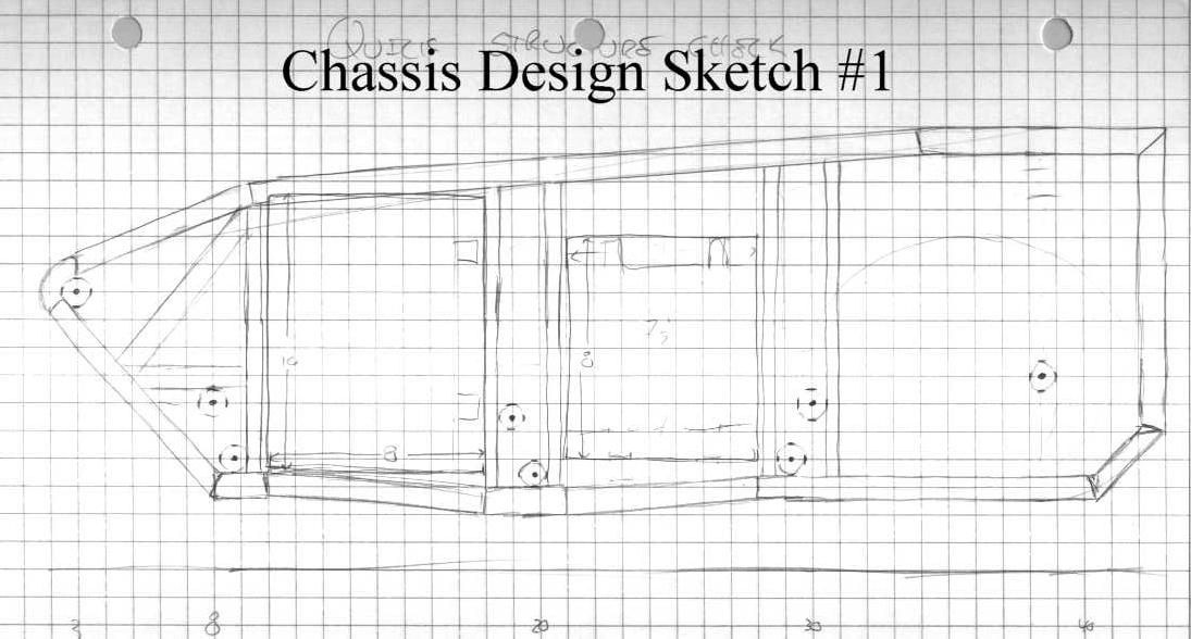
| A very early chassis sketch. For this design I was planning on using leaf springs as you can see from the lateral displacement on the axles. Only one major problem -- there isn't any room for the motors. Time to try again. |
 |
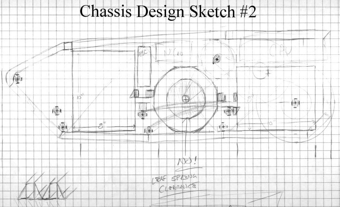
| Here I thought I could squeeze the motors into the middle. This would have given me room for a two stage gear reduction, but there was some leaf springs that were already occupying that space. That just won't do at all. |
 |
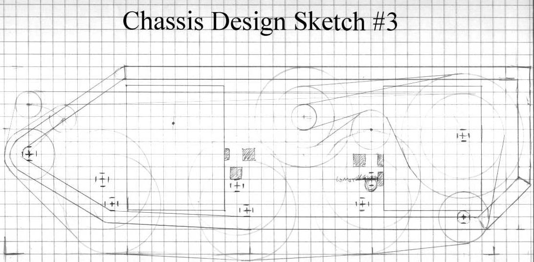
| At this point I gave up on a two stage gear reduction -- there just wasn't enough room to accommodate it. This was a promising little design, with an idler sprocket and a bigass driven sprocket for the needed gear ratio. Now, I figured, I just needed to figure out where the chassis support members were going to go. |
 |
| Here you can see I've tried my best to put chassis members in to support all the necessary locations. This was really hard to do with the leaf springs -- they have strange mounting requirements and introduce a lot of multi-dimensional displacements that really buggered things up. |
 |
| So, because leaf springs were causing so much trouble, I ditched them. Here I've moved on to a design that uses a linear-travel suspension. As you can see, this cleans up that chassis design a great deal. |
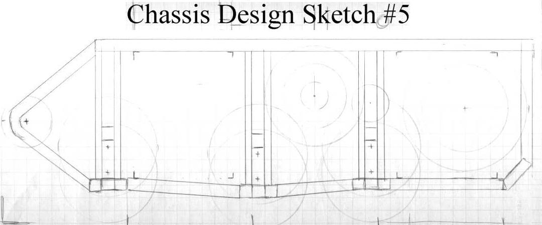 |
| With this simplification, things start to fall into place much better. This sketch looks like just another iteration, but is the first of three layered sketches. This is the side of a chassis design that I thought had enough promise to begin examining the internal details of the structure. |
 |
| This is a side view of the same design iteration about one quarter of the way into the side. This shows the structure that will support the motors. |
 |
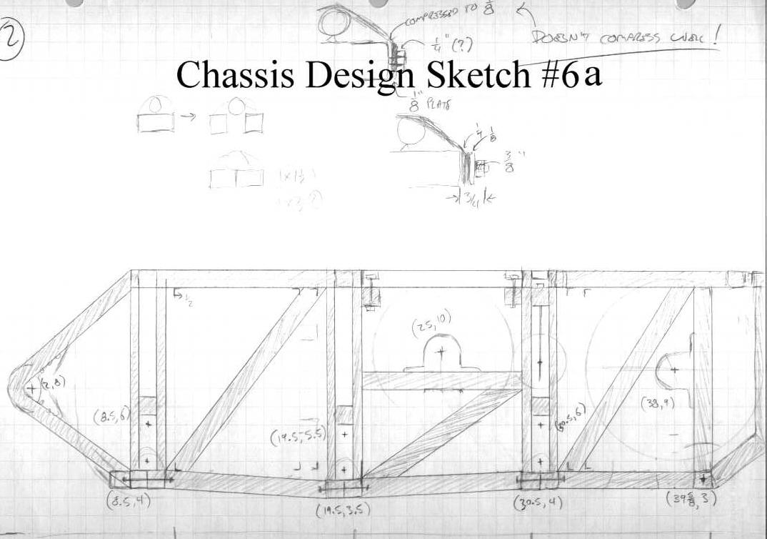
| And this is the third view of the same design iterations, showing the structure along the plane that the drivetrain will be running in. This shows the drive and driven sprockets as well as the idler sprocket. |
 |
| This is the last sketch of the chassis designed around my small batteries. This is a fairly refined design, and this sketch was the basis for a fully defined solid model of this chassis iteration. Unfortunately, when I discovered the battery miscalculation, it had the be thrown out. |
 |
| Now came the big question: How do I cram batteries this much bigger into the design without making the robot too big to fit through doors? Strike number one here fits the batteries, but not the motors. |
 |
| Strike number two fits the motors, but the drive wheels will impact the ground wheels when the suspension compresses. |
 |
| This try went a little better. There's some good stuff going on here, but I'm still stuck thinking inside a (literal) box. Everything here fits inside this nice rectangular outline. I found, however, by eliminating a good chunk of the aft structure and putting it into another piece, things worked out much better. |
 |
| By axing this chunk of chassis, it gave me much better access to the motors and dirvetrain for gear-changes and maintenance. This design is starting to look a lot like the final one. |
 |
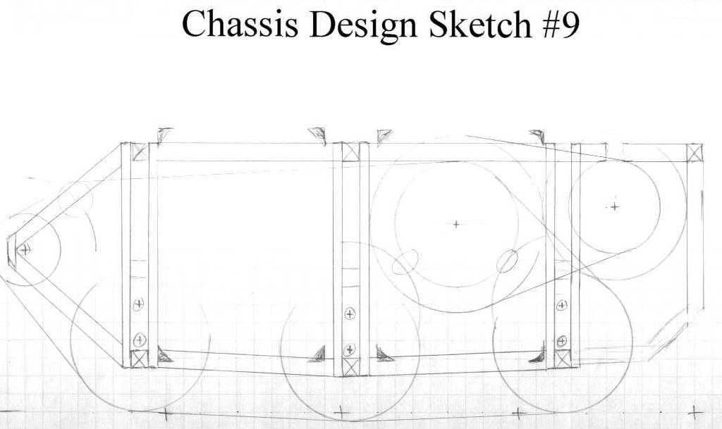
| A few tweaks and refinements and I'm starting to feel really good about this design. |
 |
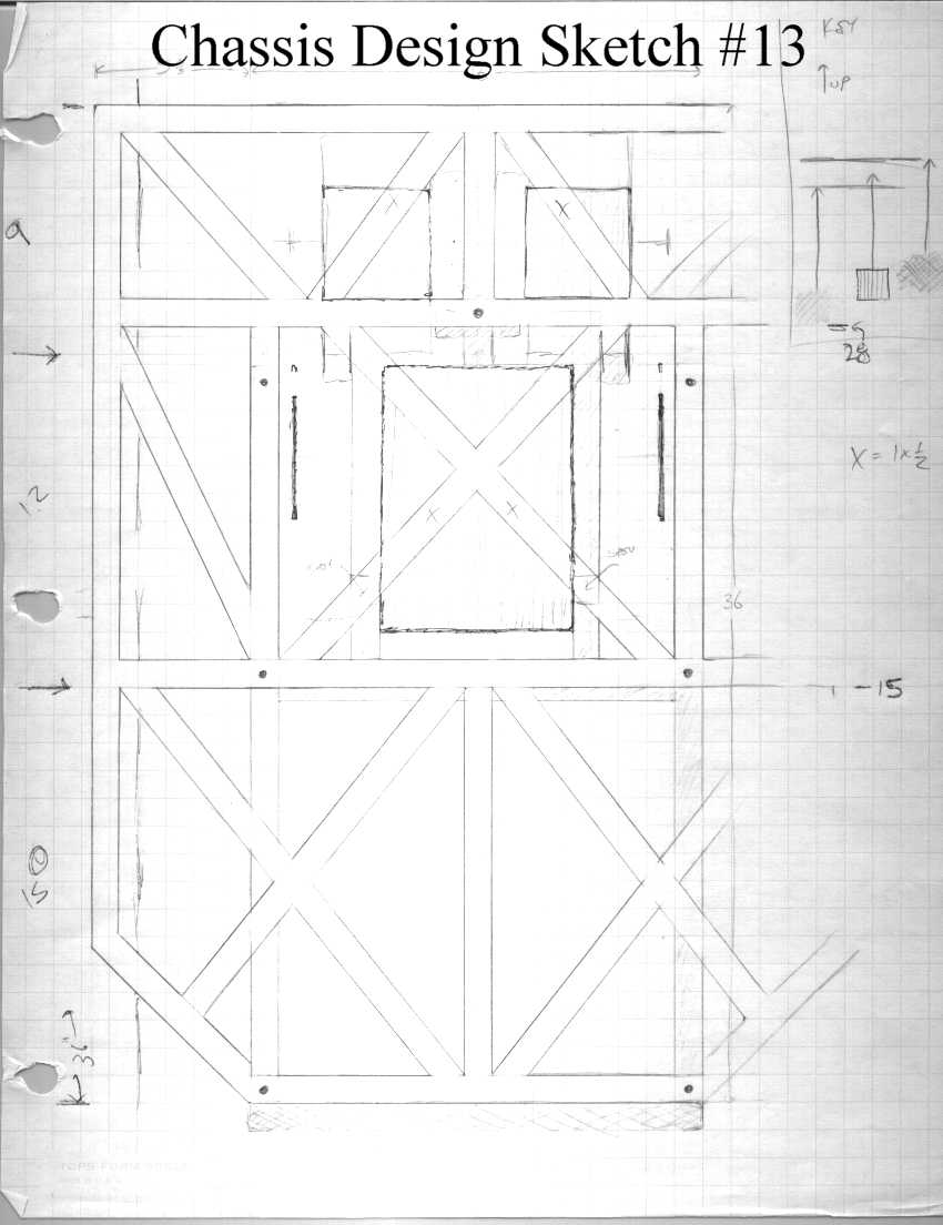
| This sketch shows a top view, and how I'm going to lay out the platform piece. This piece will have the structure that was removed from the bottom piece and will also provide a place for any passengers to stand. I plan on plating the whole piece with 1/4 inch thick lexan. |
 |
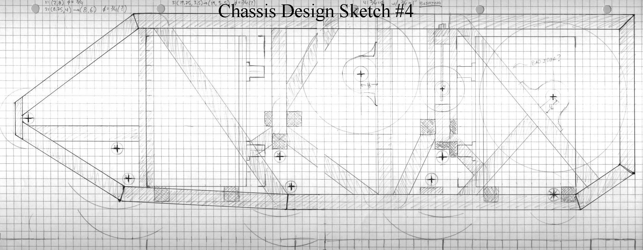
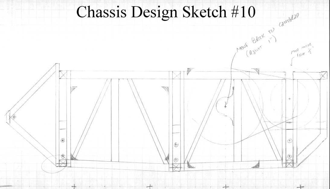
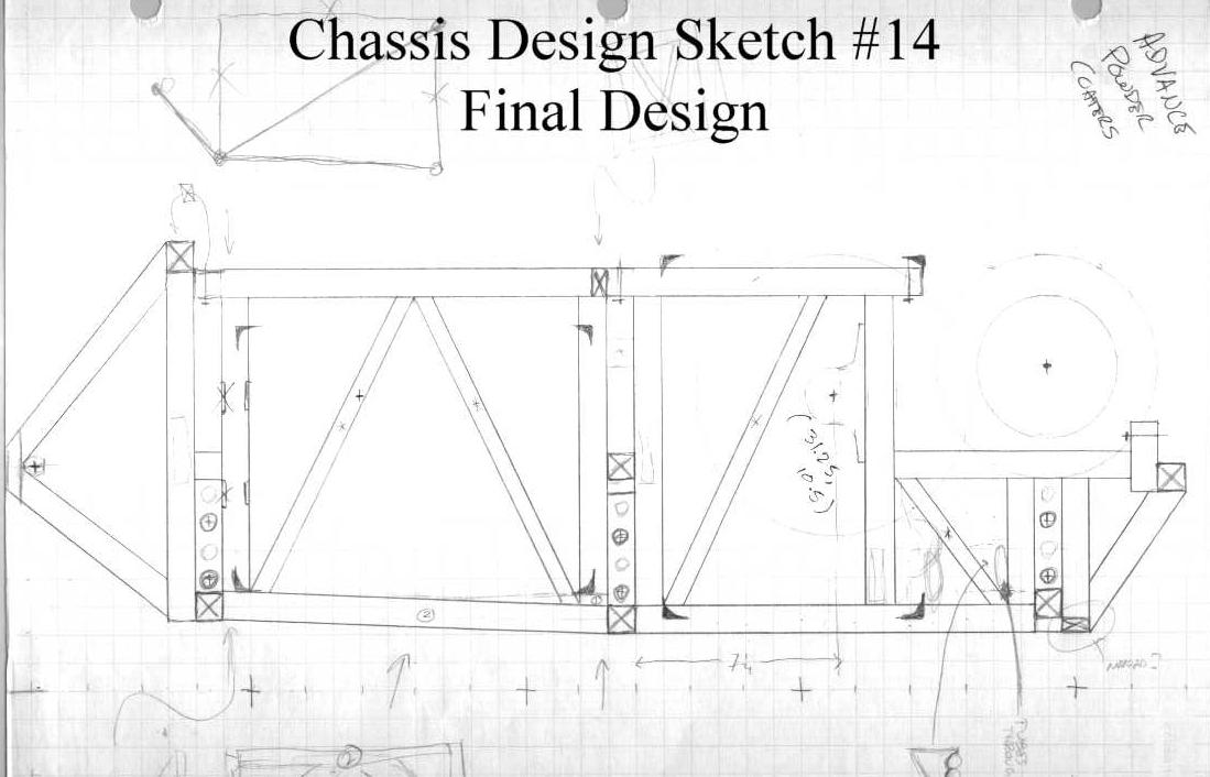
| Here is the final design sketch. This view shows something very close to the structure that I will actually build. There have been a few tweaks since the time I drew this, but it has remained largely unchanged. |
 |
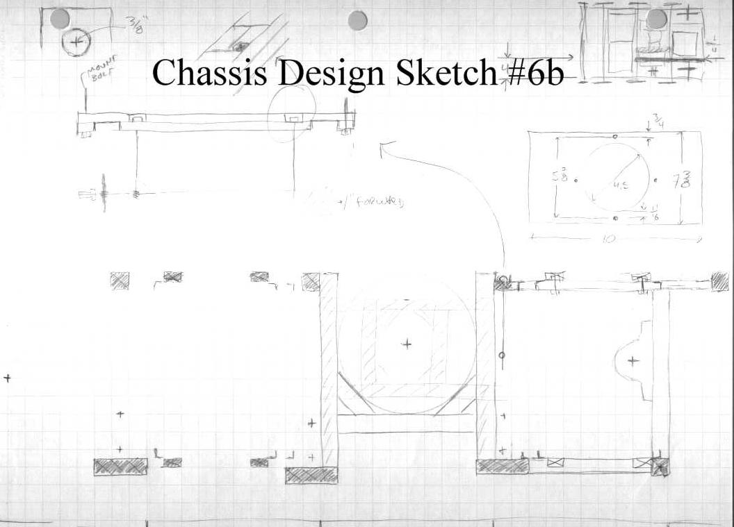
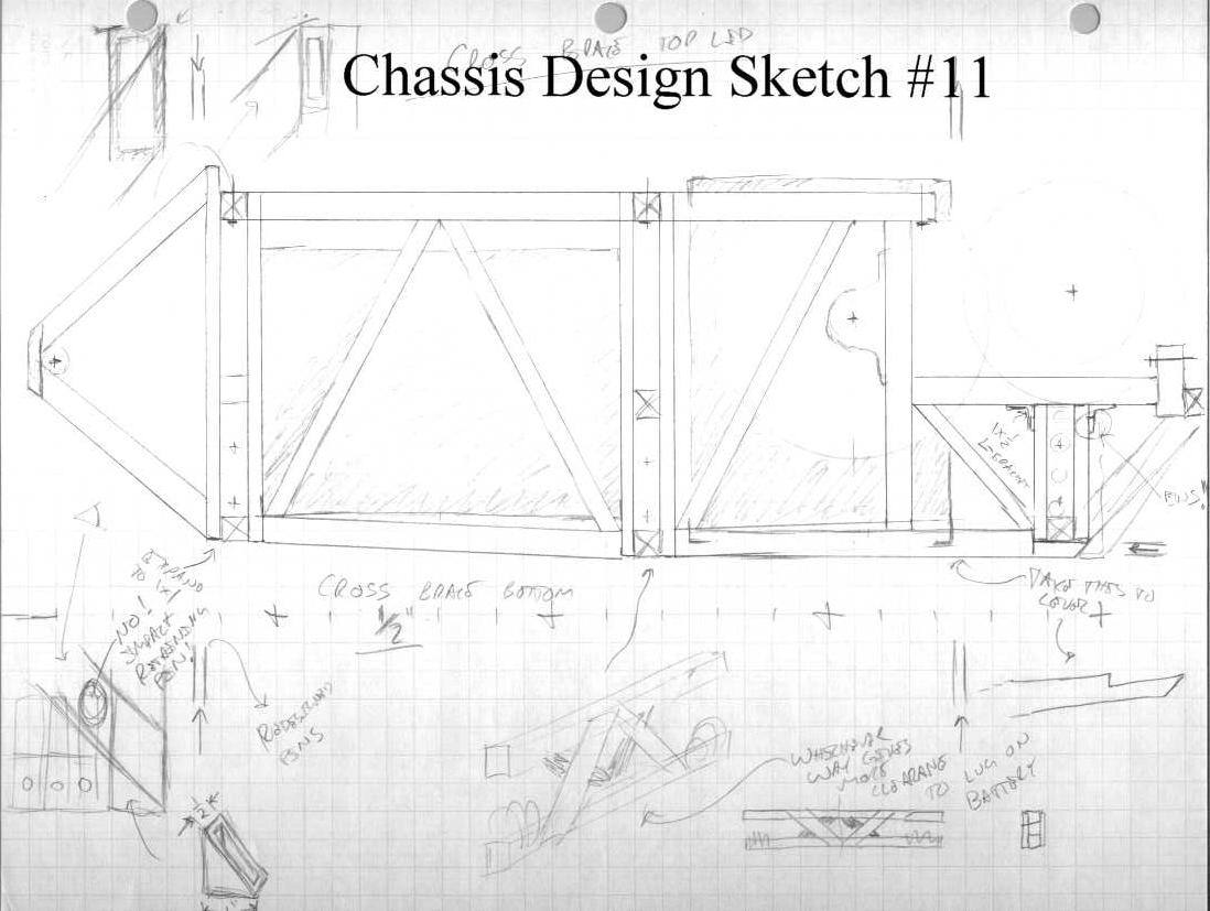
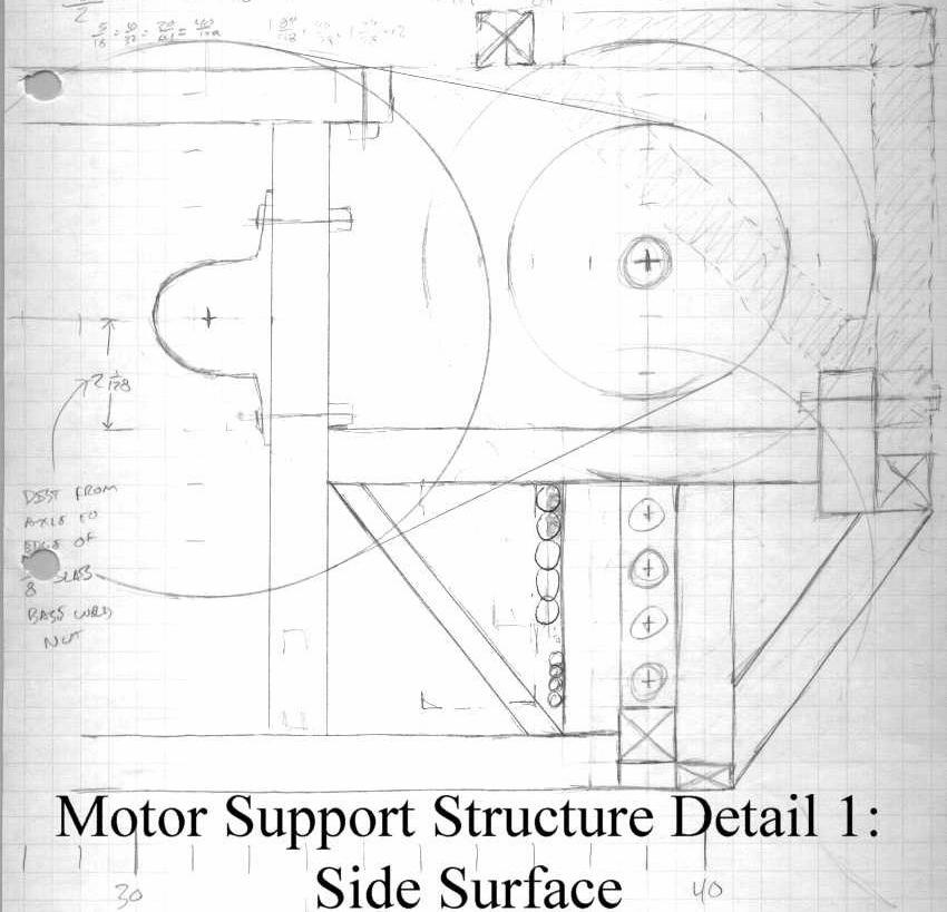
| This is a close-up of the motor support section of the chassis. This area is of interest because in has the more complicated structure on other planes. |
 |
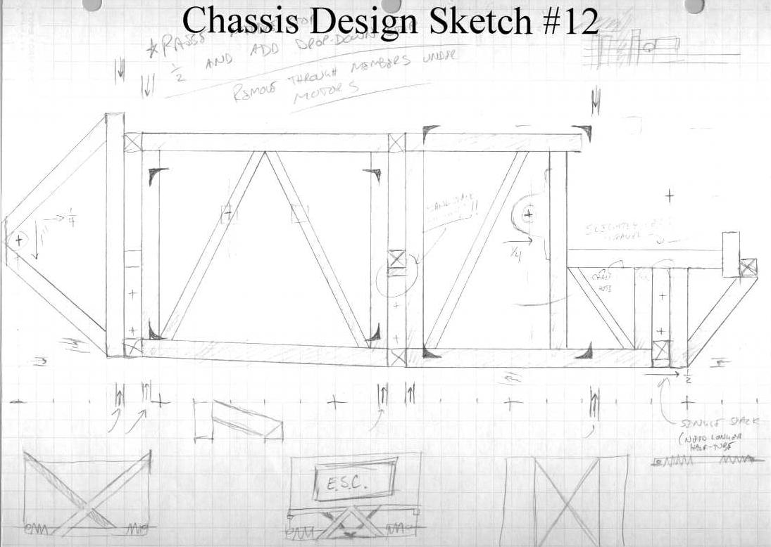
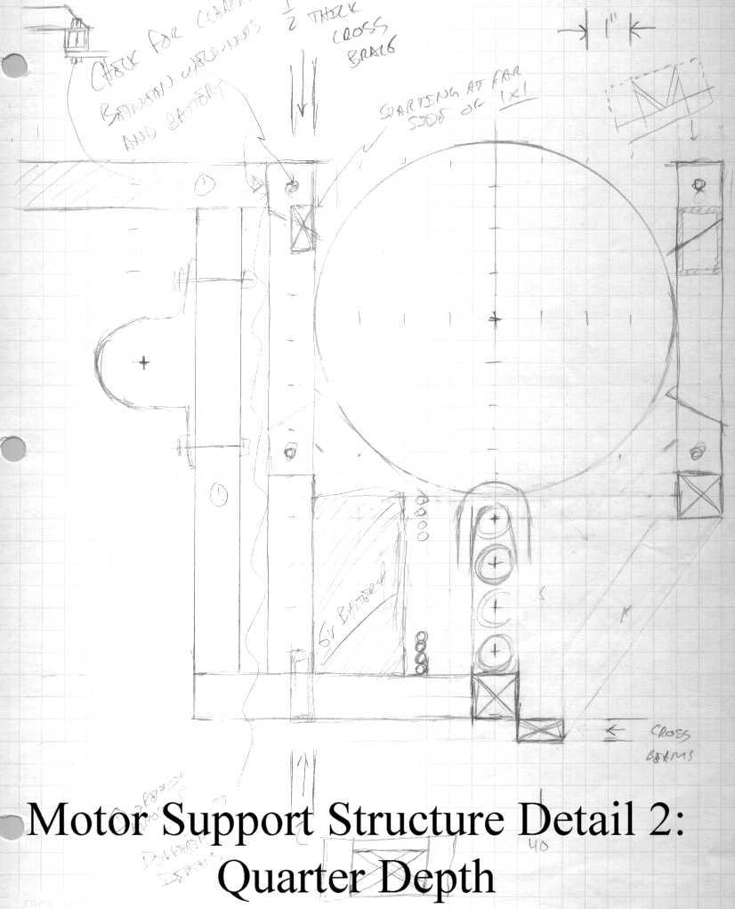
| This is the same section of chassis as the previous view, but at a depth of a few inches into the chassis. This shows the structure that will support the motor was well as the members that will support the drive axle. |
 |
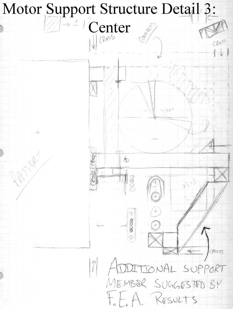
| This is the third view of the motor support structure, showing everything at the center plane of the chassis. This shows where I added a support member due to unacceptable stress distributions found during the finite element analysis of the structure. |
 |