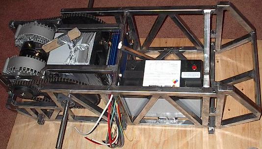
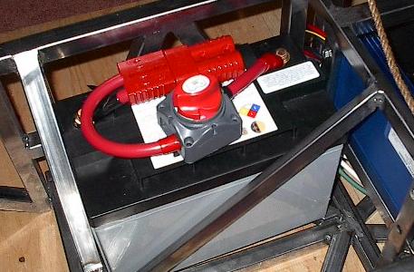
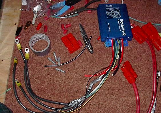
| Well, with the chassis pretty much done, it's time to move on to other pursuits. Today, I'll be wiring, starting with the speed controller. Here it is mounted up. I had a little trouble with the fit because of the misalignment of the steel bar above it, but I think it'll be OK. |
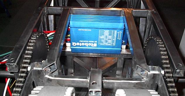 |
| I'm starting with the speed controller because it has this bundle of wiring that needs to be linked into my system, and it seemed like a good spring point. This wire is mostly 8 gauge, which is really rather thin. I contacted the manufacturer of the speed controller to ask about it, and they have assured me that it won't cause a problem. However, just to be safe, the wiring in the rest of my system will be substantially thicker. |
 |
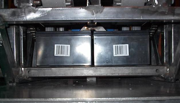
| While I was at it, I thought I'd check up on the fit of the 6 volt batteries. Here they are tucked underneath the motors, where I'd planed to mount them. |
 |
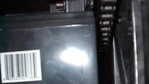
| It's kind of hard to see here, but this is one of the reasons I've decided to move the batteries. They just get too close to the running chain. I checked for this fit when I designed it, but the motors were slightly flatter than was indicated in their documentation, which throws this off. No big deal, I can just move them aft of the axle. This also gives me some extra room for my heat exchanger. |
 |
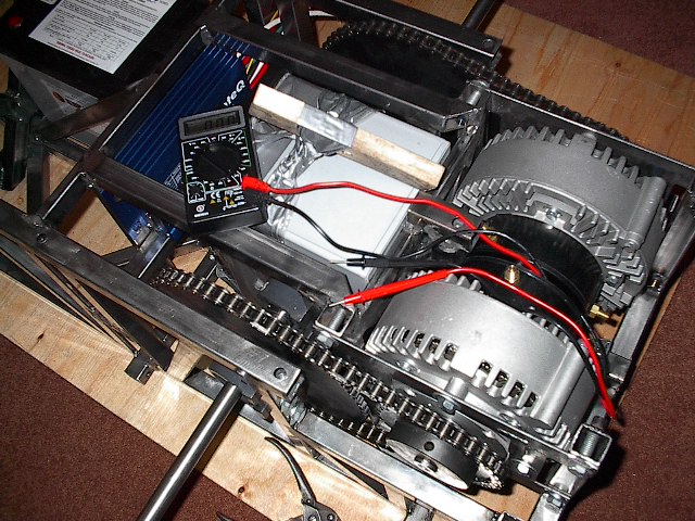
| After taking those few pictures, I decided that I didn't want to do this in my cold garage, so I've moved the whole thing inside (note the plywood -- I don't want another hole in the carpet). I've loaded the two batteries into the chassis. You can see how I've thrown together a sling out of duct tape and Saran Wrap for the aft battery. This should help me get it out without smashing the speed controller. Before the night is through, I'll make a better (yet still very temporary) one from rope. |
 |
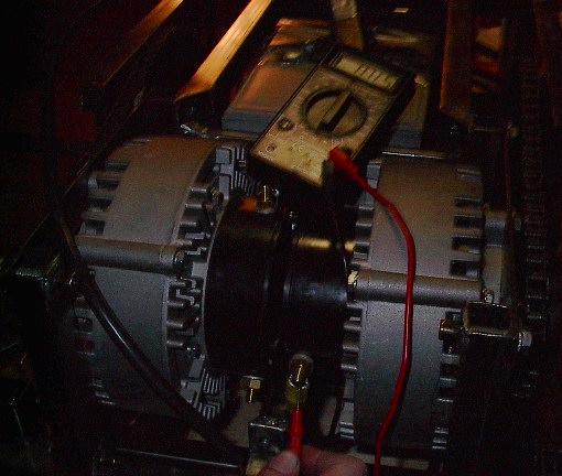
| Before I got started, I had a question about my motor setup. Which terminal was positive? What did positive even mean? Well, I've decided that I want a positive voltage to drive the robot forward. Because the only difference between a motor and a generator is the end you plug in, I can figure this out with my trusty little multimeter. I probed the terminals, turned the motor by hand, and checked the polarity of the voltage generated. Now I know which terminals need to be wired to the positive output wires of the speed controller. |
 |
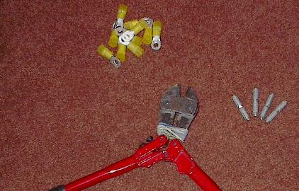
| The wire from the speed controller to the motors will be four gauge, and I'll use these four gauge crimps and ring terminals to connect everything. This system only needs to handle the current the motors draw, while the main system will need to carry double that. |
 |
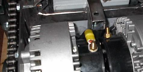
| Here's the first ring terminal and length of wire, routed through the chassis and bolted to the motor. |
 |
| This picture came out really dark, but it shows another multimeter test. I've got another ring terminal bolted to the other motor, the 4 gauge wire crimped into it, and the wire routed through the chassis. Then I used my multimeter to measure the resistance all the way through. It reads five ohms -- less than twice as much as if I just touch the leads together. |
 |
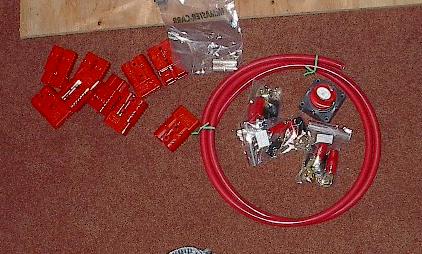
| Here's the stuff for the bigger, 1/0 wire system. You see the nine double-connectors, the big wire, a bunch of gold-plated ring terminals, and the master power switch. |
 |
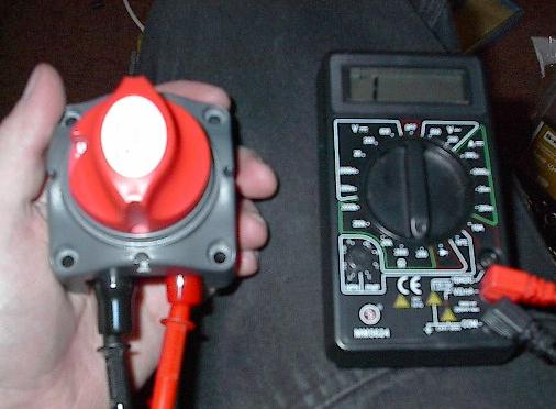
| Out comes the multimeter again. I've bolted two of my ring terminals into the switch, and checked its resistance. Here it is in the OFF position, showing an above-range resistance (essentially infinite). |
 |
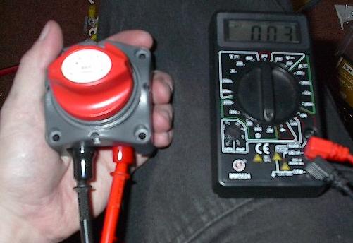
| And, when I switched it to the ON position, the resistance dropped to 3 ohms. Looks like it works. |
 |
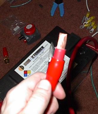
| I was very surprised at just how much work wiring was. This is a big reason why. You're looking at the stripped end of a 1/0 wire. I'm not sure if there's some secret to it that I don't know about, but it was a lot of work. I ended up spending 10 hours building today, and a lot of that was stripping wires just like this. |
 |
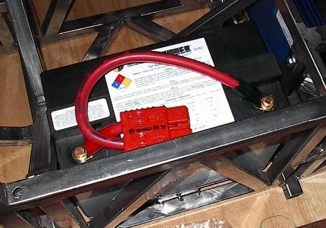
| Here's the first battery wired up. It was surprisingly difficult to bend the wire -- this stuff is beefy. I'm considering drilling some little holes in the battery handles and bolting the connector down. I haven't decided yet. |
 |
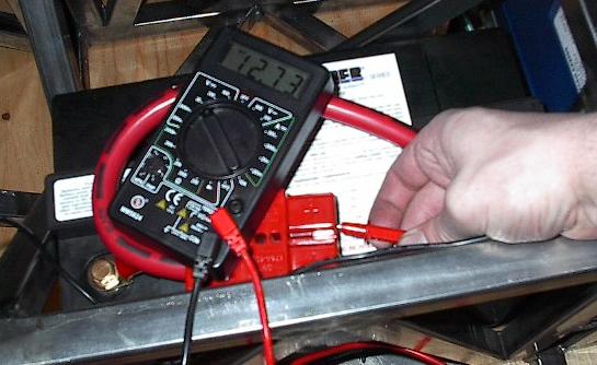
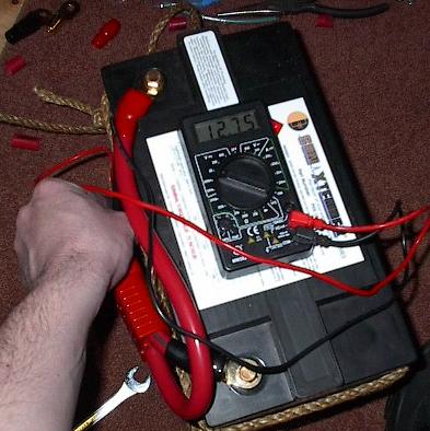
| Four crimps and two bolts went into this little system, so it's time for another check. 12.73 volts of direct current across the connector. Perfect. |
 |
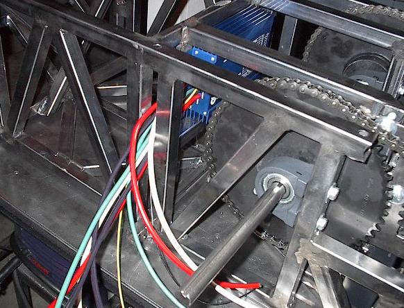
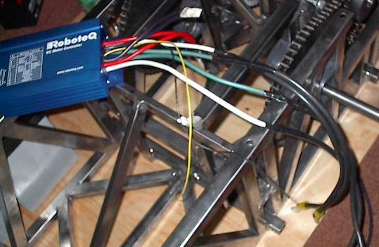
| Another battery wired. It was around this point that I realized something. You can see in the upper right the wires coming out of the speed controller. This little gap in the chassis is the path that all of the wires have to come through. Furthermore, I want to be able to take this thing apart (I need to powder coat the frame and replace broken parts (hopefully not anytime soon) and so on). My master power switch does not fit through that gap. This means that I need to come up with another solution. |
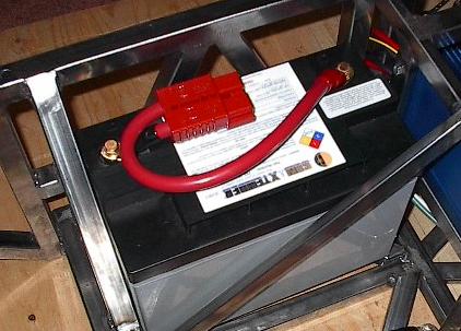 |
| The solution I came up with was to wire the switch directly to a battery. Now it will lift out with the battery, and doesn't need to fit through the gap. I'd rather have it wired inline with the speed controller, but this will do. Even if I don't bolt the connectors to the battery, I'll probably bolt down the switch. |
 |
| Here's the third battery (yes, I know, I only have two, but that doesn't mean I can't wire all three configurations). This is for the aft battery, and the connector will mount to the side of the battery. Checking all the connections, I'm getting 12.75 volts. Looks good. |
 |
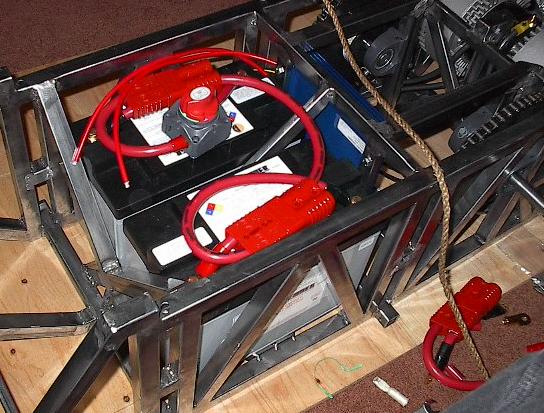
| Here are the front two batteries mostly wired up. The two red 8 gauge wires from the speed controller need to be crimped into the connector, and another length of 1/0 wire needs to run from the near battery into the aft battery compartment. |
 |
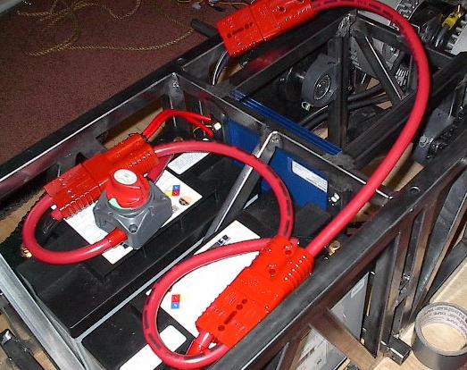
| Here the speed controller wires and crimped into the connector, and the other wire is cut. The connector on top needs to be threaded through the gap on the left of the speed controller, and connected to the third battery (that isn't there). |
 |
| With all the wires cut, it's time to finish up the speed controller wiring. I didn't crimp the wires because it was too hard to get to them. Here it is with the connections duct-taped. With it removed from the chassis, I should be able to crimp on some nice stable connections. |
 |
| Here it is after I've cleaned everything up. Each of the four wires that was duct taped has been crimped using the four gauge crimps, and then covered in electrical tape. These should provide good, strong, low-resistance connections for the motor cables. After this, I wired everything back up, but I didn't take a picture. I won't be able to wire it all properly until my third battery gets here, so you're not missing much. |
 |