|
Build Log, Day 48 (04.07.2005)
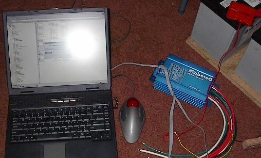
| The speed controller showed up today. I finally, after nearly two weeks, have a replacement for this damn thing. This entire ordeal has been a nightmare, but now, $520 later and with one day left, I have it. Here I'm downloading a new version of the software to the board. I'm also checking out its sensor readings to make sure everything's cricket. Looks like it's all ok. |
 |
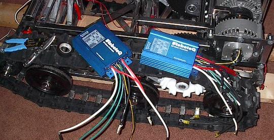
| Now it's time to start wiring. This is actually quite a bit of work, but someone's got to do it. I'm using the old, burned out controller as a template for the new one. The wires that run to the motors have been changed dramatically at the suggestion of Cosma, the tech support guy from RoboteQ. I've reduced the gauge of the wire to 4 and included a lot more length in small coils at the back of the robot. This should increase the resistance and inductance of the motor circuits slightly, protecting the controller. |
 |
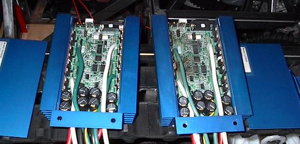
| Another side-by-side comparison of the controllers. I'm stealing the faceplate off of the old one (I modified it slightly to fit the mountings on the chassis), and as long as I had it apart, I'd check out the insides. It looks like everything is in order. For the record, the left shows what a speed controller should look like inside (green), while the right shows what a speed controller shouldn't look like inside (black). |
 |
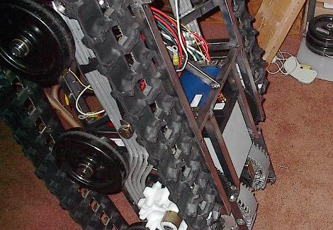
| Of course, once the wires were all crimped on and cut to length, it was time to mount the controller in place. I can't actually route the wires yet, because they need to fit tight around the aft battery, so it has to go in next. |
 |
| I've found that the aft battery is incredibly difficult to load into place unless you stand the whole thing up like so. This way, I can just load the mount strap into the cavity, slide the battery in, attach the terminals, and bolt everything into place. It goes pretty smoothly, but it is a bit unnerving laying under this thing getting the bolts tightened. |
 |
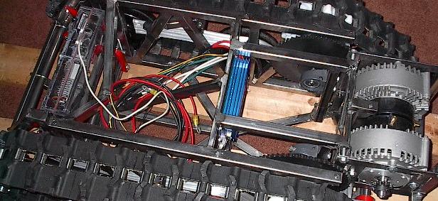
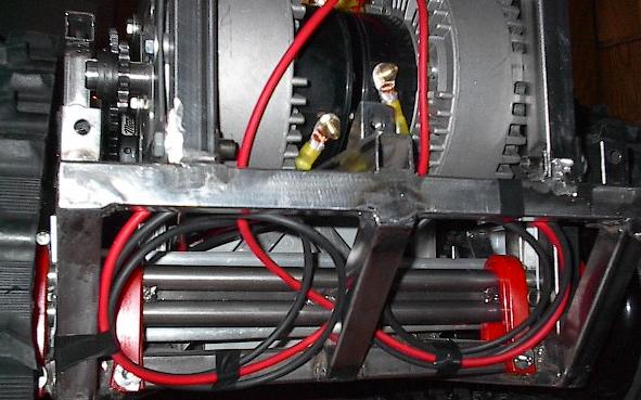
| With the battery in place, I was ready to run the wires back to the motors. If you believe what RoboteQ told me (eventually), this should give the speed controller a few additional microseconds to protect itself in the case of a surge. It isn't as pretty as it was before, but if it'll save me from smoking out another $500, I'll be happy. |
 |
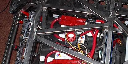
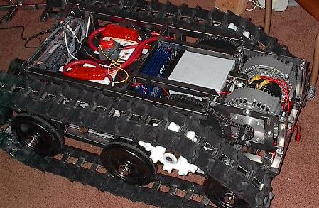
| Now it's time to get the last of the main bits in -- the batteries and associated wiring. I dropped them in, clipped in the big 1/0 wire, and ran some wires for the emergency kill switch. I also took a minute to hook up the laptop computer and crank up the motors at low speeds, just to make sure the wiring was right (it was). |
 |
| You can't really see it here, but I've modified the front sheet of Lexan in two ways. First, I've mounted an emergency kill switch in it. This little component (worth about five cents at Radio Shack) could very well have saved me from the testing disaster two weeks ago. I've also cut a big hole over the master power switch so that you can turn it on and off with the top plate on. |
 |
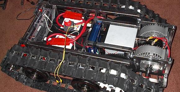
| Finally, now that I know that everything works, I've connected the chain drive. It is a nice, safe feeling when this isn't hooked up, but now that it's all confirmed, it's time to add it. |
 |
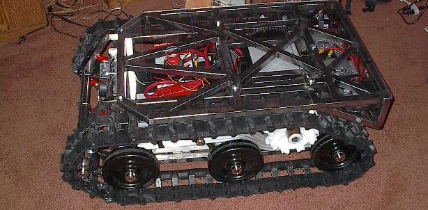
| Here it is all put together. Now we just have to iron out some final software stuff and we're ready to go. We'll load it into the car and go present this puppy at Senior Project presentations tomorrow. Wish us luck! |
 |
| End, Build day #48 (04.07.2005) |
| Progress: |
Finished final assembly. |
| Time: |
8 hours |
| Total Time: |
326 hours |
| Next Steps: |
Present it. |
| Status: |
I think we made it. |
|