|
Build Log, Day 43 (03.24.2005)
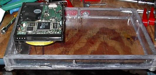
| Last night I did a bit of work to prepare for today's build, so we'll start out with that. Christina's been working with the computer system for the past few weeks, so it wasn't until now that I've had a chance to work with it. I'm loading it into the enclosure, where I'll crank it up and make sure everything works. Then I'll run a few quick tests to make sure that the power draw and temperature increase are what I expected. Then it's time to finalize the box and mount it in the chassis. |
 |
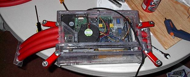
| Here it is all wired up. There are going to be three points of entry that I need to create for this box before I seal it, as you can see in the wires here. I'll need to mount the power switch, which is the black and blue wire on the bottom right. I'll also need to cut a hole for the main power plug, which you can see on the right (white and black). Finally, I have to seal the serial interface cable in. It's a little harder to see, but it's the thick black wire at the top. |
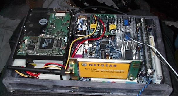 |
| Now that I had it all set up, it was time to wire it and see the thing go. This gave me a chance to check the air flow through the pump, the reliability of the voltage on the DC power supply, and the wireless communication. The pump works just fine, and the wireless came up easy too. The voltage, on the other hand, was a problem. I think there might be something wrong with one of the two six volt batteries I'm using. |
 |
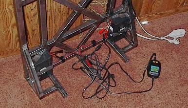
| Time to start diagnosing the battery problem. Maybe, just maybe, I'm drawing way more power than I think I am. So, it's time to bust out the trusty multimeter and check. I've put it into the circuit, unwired the fuse, and set up the current detection. I'm reading a nice steady 2.5 amps continuous, with peaks of about 3 on boot up. Exactly what I thought I'd be drawing. At this rate, the batteries should be getting around four hours of operation -- it craps out after ten minutes. |
 |
| Well, maybe the batteries were undercharged or something. I hooked them up the the smart charger and left them until they'd gotten a good, long maintenance charge over and above full. |
 |
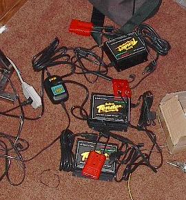
| Now that I had some time to kill, I thought I'd set up the other chargers. It was a fairly simple job -- I just wired one of the bigass Anderson PowerPole connectors to each one. This is way overkill, but it forces the user to unplug the battery from the system before charging them. It's a safety feature that is worth the extra bulk and expense. That does it for last night's work. The next step is to clip the track, and that's going to call for a lot of hammering, so I'll wait until the daytime. |
 |
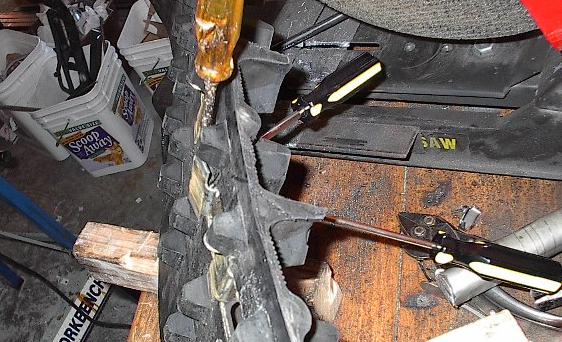
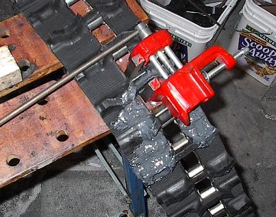
| A little sleep and a lot of hammering later, and here we are working on the clips. This is a scrap of track that I cut off and had discarded. Now I'm prying off two metal clips to use on the seam of my tracks. Each seam bisects one of these clips. If I replace it with a whole one, it should provide a lot of extra strength. They were a bear to get off, but with the help of three screwdrivers and two hammers, I did it. |
 |
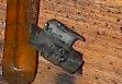
| All that work for this little thing. Well, if how hard it was to pry off is any indication, they should be good and strong. Now I need another one. |
 |
| An old bench vice (sans the bench), a cheater bar, and some elbow grease later, and I'm well on my way to having the clip crimped down. It isn't a perfect solution, but it'll get the job done. |
 |
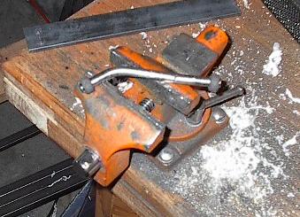
| For one last little push, I've loaded the thing up into the bench vice that is actually good enough to get a bench. I put some muscle into it and got a pretty good closure -- not perfect, but pretty good. |
 |
| Unfortunately, during the process, I kind of mutilated the poor little handle on the vice, and bent the screw. This was really just finishing the job I started when I tried to crimp the pipe shut for the tensioner arm. Oh well, I can fix this, I just don't have the time right now. Fortunately, I did it just as I was finishing up the last crimp -- the tracks are done! |
 |
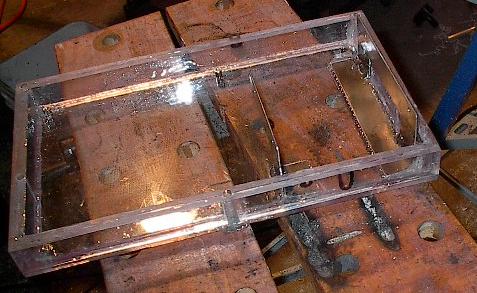
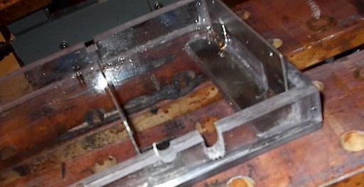
| Time to finalize the VIA enclosure. You can see where I've drawn in black on the plastic. I'll cut these spots out, and the run the wires and switches through there. I'll seal them in with glue so that I don't let any water in. |
 |
| There's the three notches (two in front, one in back). |
 |
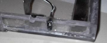
| Here's the power plug for the computer routed through the box and sealed into place. It went really well -- looks like this method should work just fine for the other cables. |
 |
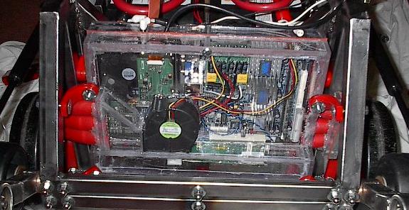
| With all the cables fitted up real nice like, I was able to finally get everything enclosed in the box. This will look really cool living right in the front of the robot. |
 |
| And here it is. This thing is way more of a pain that I'd anticipated. Getting it disconnected from the shock mounting and the heat exchanger and then wrestling it out of there is a huge ordeal. If I could start over, this entire system would get a major redesign. Unfortunately, I can't, so here it is. |
 |
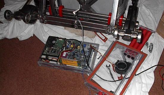
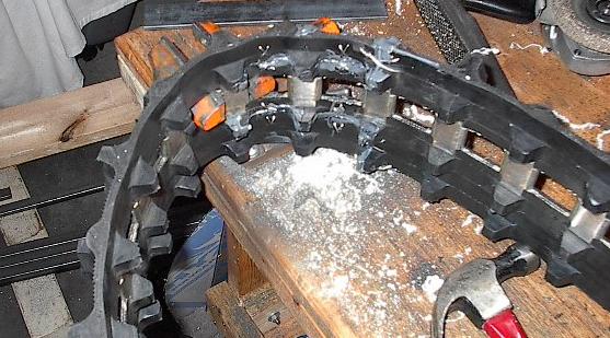
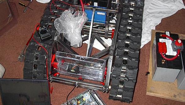
| The computer system is all wired up, and Christina is working away at the software end of things, so I'm on to my next major project -- the track. I've got the springs compressed and lashed, the tensioner arms freed, and the robot stood up so that I can get at all the wheels. Let's see if something will actually go according to plan for once. |
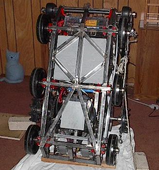 |
| They're on! It was a lot of work, and it took three people (which is why there wasn't anyone to take pictures during the intermediate steps), but they went on. It actually did go more or less according to plan, with a few minor modifications when necessary (*creak* *pop* *snap* "What's that noise?" "I think it's the track creaking" "I think it's the rope breaking" "It IS the rope breaking! Stop pulling!"). |
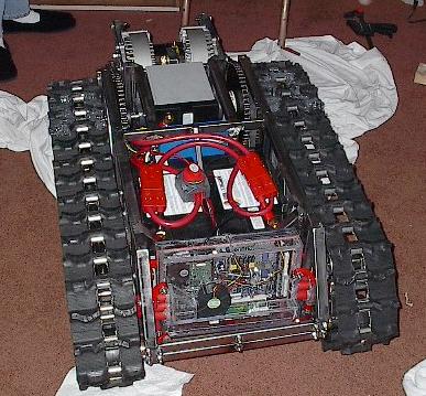 |
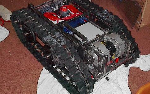
| They look great. The tensioner arm is keeping the angle I expected, the track is nice and tight. Unfortunately, there are some unseen things that are causing problems. The tension is compressing the suspension more than I'd expected. This isn't too big a deal, but it does make the robot teeter a little more than I like. More importantly, the tracks are snagging on the tensioner arm. They'll still pull through, but they catch every 2.52 inches, which makes for loud and very inefficient driving. |
 |
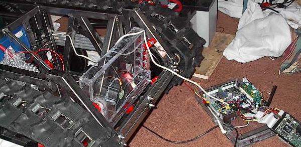
| It has been a long time since the last picture. I have this problem where when things go horribly wrong, I forget to take pictures. We're still having problems with the six volt batteries (I'm pretty sure one's a dud), but I really wanted to try this beast out. So, I tapped one of the big 12V batteries to power the computer system, and ran the speed controller off of its built-in DC/DC converter. We plugged stuff in, smelled smoke, the serial cable got hot, and I grabbed a fist full of wires and pulled (that's the real emergency shutdown). After a lot of problem diagnosis and consulting people who know more about electronics than I do, I think that somehow the ground wire in the serial cable managed to get current from the computer system all the way to the sub-ground, which is 12 volts below the computer's ground. Anyway, stuff isn't working now, and we're trying to figure out just exactly how much shit we're in. |
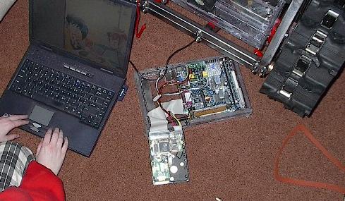 |
| This is the robot in safe mode. I've pulled two of the three batteries, everything is operating on the one remaining. The laptop is wired to diagnose the problems. And we're pounding our heads against the problem and not making a lot of headway. Finally, by exhaustive search, we think that it might be the serial cable. That would be fantastic -- the computer system would be in the ballpark of $200 to replace, depending on what was damaged, while the speed controller is $500. A new cable costs $15. |
 |
| There's one easy way to find out if it's the serial cable. If we run the system without that component and it works, then that was the problem. Of course, in order to do that, we need a new cable, and it isn't standard. It's a nine pin RS232 serial to a male 15 pin. However, it's late, I don't want to wait to get one shipped, and I don't have a spare -- that means I make one. I have an old game pad with the 15 pin connector, and a serial mouse that I can cannibalize for the plug. Unfortunately, for all the game pad's pins, the cable had only six wires in it, and they're not the ones I need. |
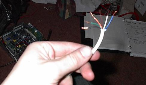 |
| At least the serial plug was of more use -- it had nine pins and eight wires, and I don't care about the missing one. So, I took a sharp knife and cut open the 15-pin plug, pried out the pin-holder, soldered the pins I needed to some wires, and crossed my fingers. Now it's time to test it out. |
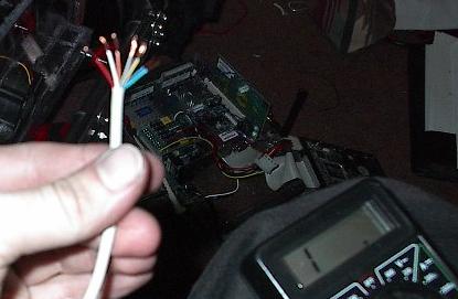 |
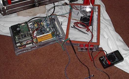
| Here's the little mess of a test-bed we've set up. The new, homemade serial cable is wired up, and we cranked up the software. Remarkably, everything worked! It was the cable, and now we have a new one. It is really late, and time to go to bed. |
 |
| End, Build day #43 (03.24.2005) |
| Progress: |
Computer wiring, finished track seams, installed tracks, cooked the serial cable, figured out that we cooked the serial cable. |
| Time: |
17 hours |
| Total Time: |
276 hours |
| Next Steps: |
Test, pray. |
| Status: |
Behind schedule, ten days |
|