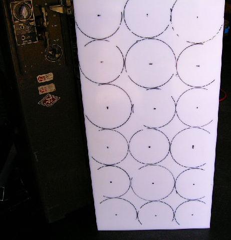
| First up today are some improvements to my wheels. They've got this annoying tendency to throw tracks now that I've reduced the tension, so I'm trying to put a stop to that. This is a sheet of three-quarter inch thick low-density polyethylene that will, hopefully, end up looking a whole lot more like wheels. Each of the six wheels will get three new layers of stepped diameters. Don't worry, it will make a lot more sense when you see it. Notice here how each of those circles roughly sketched on the plastic are not the same size -- there are 12 seven inch circles and 6 eight inch ones. I think I've got optimum spacing worked out. |
 |
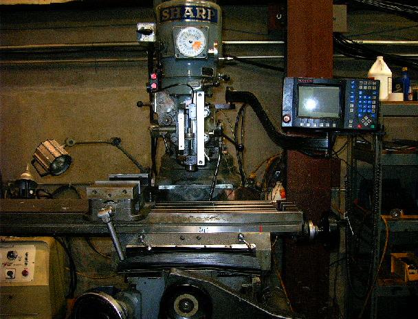
| And this is the tool that's going to help me make that large rectangle into eighteen perfect circles. This is an Acu-rite mill with two-axis CNC control. This means I can program it to cut the circles and drill the bolt pattern and all I have to do manually is set the depth. Technology is such a wonderful thing. |
 |
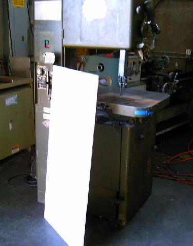
| However, before my plastic goes on the mill, it has a date with this -- the ban-saw. I'll use this to cut out rough circles which I'll then clean up on the mill. |
 |
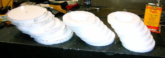
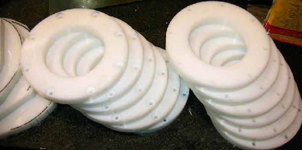
| I forgot to take pictures of the in-between steps, but here's the eighteen parts I'm working on. The 12 on the right are already finished, but the 6 on the left are still just roughed out. They're going on the mill next. |
 |
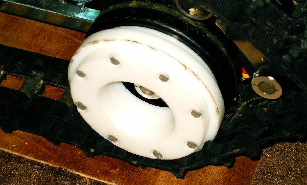
| Here's a better shot of the finished wheels. You can see I didn't just cut them into circles, but also drilled a bolt circle, counter-bores, and cut a large pocket out of the middle. The outside diameter will roll inside the snowmobile track, the inside diameter provides clearance for the axle and shaft collar, and the holes will be used to bolt everything together. |
 |
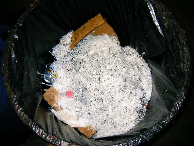
| By the time I was done with all eighteen parts, I'd made a lot of chips. I had to cut out a whole lot of material to clear out the middle and to clean up the outside diameter. This picture didn't turn out very good, but that's a full-sized garbage can about a third full of white LDPE shavings. |
 |
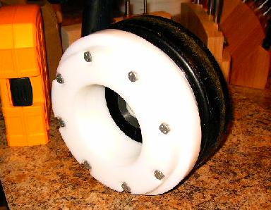
| Here's one finished wheel. I forgot to take pictures of the modifications to the existing black wheels, but it involved drilling eight holes, counter-boring them, and pressing in steel T-nuts. A bolt is passed through a seven-inch white wheel with counter-bores, an eight-inch white wheel, another seven-inch white wheel, and finally through the eight inch black wheels. The holes were all drilled to nominal size, which left them extremely tight around the bolts. This should get accurate enough location of parts for my purposes. |
 |
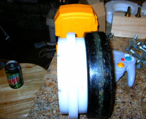
| This shows the profile of the modified wheel. This is what I did all that work to achieve. By stacking different diameter plastic circles, I've got a wheel that should really hang on to the snowmobile track. |
 |
| And here it is on the robot. Looks like everything fits. |
 |
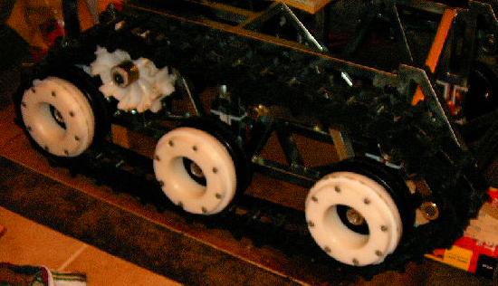
| And here's all six installed. They look like they'll work great, and they look damn sharp to boot. They were a lot of work, but I'm really happy with how they came out. |
 |
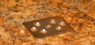
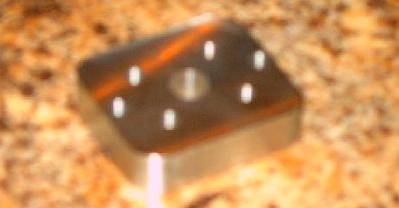
| Next up are some power-switch modifications. I don't really want to cut a big hole in my nice Lexan sheet for the power switch, so I designed this to fit onto a cam latch that I'll set into the Lexan. The middle hole is actually a square (it's a shame this picture didn't turn out better -- square holes are a lot of work and this one came out great), while the six outer holes loosely fit over socket head cap screws that fit in another part (more on that later). |
 |
| I modified the power switch by milling four notches into its sides. These will capture a mating part by virtue of the same socket head cap screws that the above part fits over. |
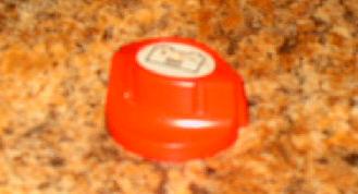 |
| This is the final part of the power switch assembly. The screws thread through this and around the red power switch. The notches are located such that this retains everything very securely. The plate mates with the heads of the screws. |
 |
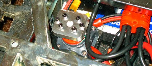
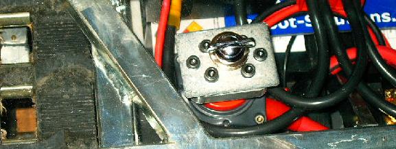
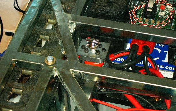
| Here's the bottom half of the switch assembly. The red switch is locked into position on the robot and the aluminum block is attached using the six socket head cap screws. |
 |
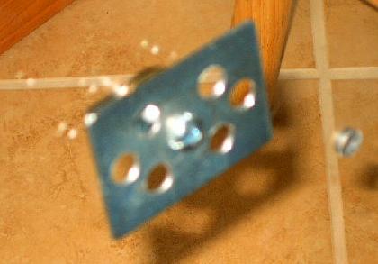
| And here's the top half of the assembly. The flat plate is bolted onto the cam latch in the Lexan. When I bolt the Lexan down, this should just slide over the bottom half of the switch. |
 |
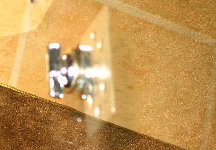
| This is another shot of the same thing. The only thing sticking through the Lexan will be this little switch, but it will turn the plate on the other side, which will turn the aluminum block, which will turn the red switch, which will turn on the robot. Pretty neat, huh? |
 |
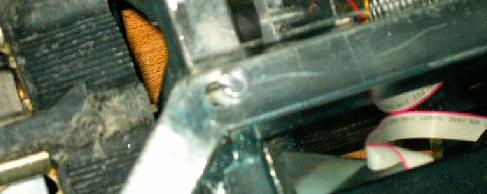
| The best part is that they go together! Well, until you look closer... |
 |
| ...the Lexan sheet doesn't actually fit anymore. The switch shifts everything off by about a quarter of an inch so I can't bolt it together. All I have to do to fix it is more the power switch's location. It's a bigger job than it sounds, but I don't have any pictures and it isn't interesting, so I'm prepared to just leave it at that. |
 |
| With just a few tweaks everything goes together and works like a champ. Now if someone spills a drink on my robot-slash-coffee table, there won't be a big gaping hole for it to pour down directly on the high-current wiring. Neat! |
 |