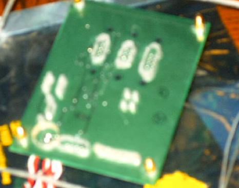
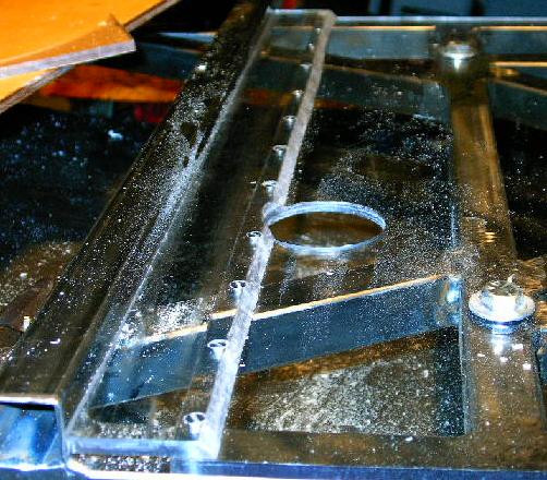
| Today I did a whole lot of plastic work. To start with, I made a few little modifications to this little mounting plate for the uMOB2. See, the USB plug on the board was a hair higher than I expected, and when I added the steel cross-bars the other day it resulted in a really tight fit. Bolting the top panel down put pressure on the USB plug and flexed the uMOB2 board slightly. It was OK as long as it just sat there, but I was worried that an impact would cause problems. In any case, to make a long story short (too late), I needed to mount the circuit board flat against the acrylic, and that meant that holes had to be drilled to allow for the solder sticking out of the bottom. |
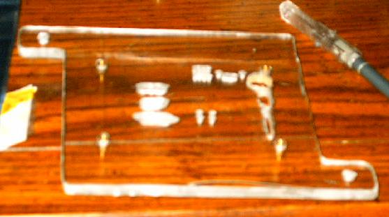 |
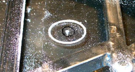
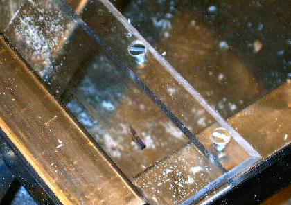
| This is the desired result. The picture came out really fuzzy, but you can see how the holes in the plate let the solder on the board drop down into the acrylic. The end result is that I can lower the uMOB2 board about 3/32 of an inch, which is just enough to provide clearance for the USB cable. |
 |
| I put everything back together and it looks just peachy. The next major project is to modify the sheets of Lexan that used to cover the top so that they can fit over the new top panel geometry. |
 |
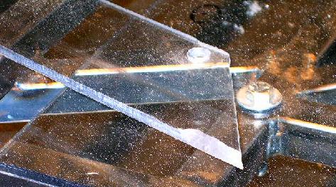
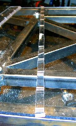
| For this modification, I want to use mechanical fasteners (also known as screws). After all the trouble I had with the epoxies and other glues I used for the VIA enclosure (I'm still not happy with its integrity), I want to try something more reliable. Because I was going to have to set screws into the edges of the 1/4-inch, it was time to do a little empirical research. I took a piece of scrap Lexan, drilled three holes (1/8-inch, 7/64-inch, and 3/32-inch), countersunk the edge, and drove #6x1/2 wood screws into each hole to judge how the plastic would hold up. |
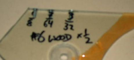 |
| I was hoping that you'd be able to see the stress distortion in the clear Lexan if I took a big enough picture, but it looks like no dice. Anyway, you'll just have to take my word for it -- the 7/64-inch hole looks like the way to go. The 1/8-inch hole was too spacious and there wasn't enough thread-depth for a really strong joint, while the 3/32-inch hole just had too much friction. With that all figured out, it was time to forge ahead... |
 |
| ...or so I thought. This is a picture of my laptop -- a trusty old companion that's been recording my notes in class and accompanying me to LAN parties for over three years now. Next to that little green light that indicates power there is a little orange light that indicates when the battery in charging. It hasn't lit for about a month. Since I graduated, this laptop doesn't see any time away from an outlet, so I didn't really think it was a big deal until I remembered that I needed this thing to be mobile if I wanted to run the robot anywhere other than my basement. |
 |
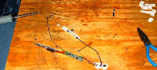
| Well, my three year warranty ran out last month, so all those little stickers that say "Do NOT attempt to service, tamper with, adjust, take apart, alter, or even think about repairing yourself" just became meaningless. I tore the pack apart and found eight little 3.6-volt lithium-ion cells, some wires, a little circuit board, and a surprising amount of fluid. The fluid is a little troubling, but it didn't burn when I got some on me, so no worries. A few seconds with the volt-meter tells me that the outer four cells are sitting at a surprisingly high 4.2-volts while the middle four read somewhere in the ballpark of 0.01-volts. Looks like I've found the problem. |
 |
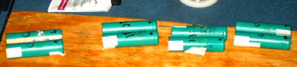
| A little research, $50, and four days later, I had these little beauties. A new battery pack, by the way, runs around $250. Note the clearly labeled positive contacts (one backwards battery and I could destroy the entire pack). |
 |
| One thing that was a little surprising was that the batteries were shipped fully charged. No big deal -- I'll just discharge them a bit. I had an old tire pump that I'd taken apart laying around so I wired it up and left it running for an hour. That should do the trick. |
 |
| This pump was, of course, rather loud and annoying, so it got to live under a cardboard box and a pile of blankets. That made the hour a much more pleasant one. |
 |
| Here's the cells I removed from the pack. You can see them labeled with polarity and state indicator marks (smiley and frowny faces). |
 |
| While the new cells were discharging, I got to work dismantling the old pack. This is the part that I'm going to re-use. For some reason, I didn't take any pictures of the reassembled pack, so I'll just give you the rundown here. Something went wrong during discharge and two of the new cells dropped to 0.01-volts. I've heard that lithium-ion cells have problems with getting run too low, so I may have destroyed them. Anyway, I assembled the pack with the six good batteries and two of the old ones that were still holding a charge. There were a few problems getting things to work together all happy-like, but I've finally gotten a reasonable level of performance out of the things. They don't seem to want to charge above 50% and at that they are only giving me around an hour of battery life, but that's good enough in a pinch, especially when you take into account the fact that I don't currently have $250 to my name and thus cannot buy a brand-new pack. |
 |
| Now it's back to work on the robot. I was never really happy with the fit of the top Lexan plates -- the holes weren't drilled in exactly the right places and this made assembly really difficult. So, for the first step in this project, I've widened the holes a bit and shifted them in the appropriate directions to remedy this problem. |
 |
| Then I took the front of the three plates (the one that needs to fit over the modified panel members) and cut a strip off of the front to fit in front of the raised portion of the top panel. |
 |
| This strip had to have chamfers cut into its corners on the ends like so. These allow the plate to lay flat over the fillet welds that hold the new steel cross-members down (you can see this on the above picture). |
 |
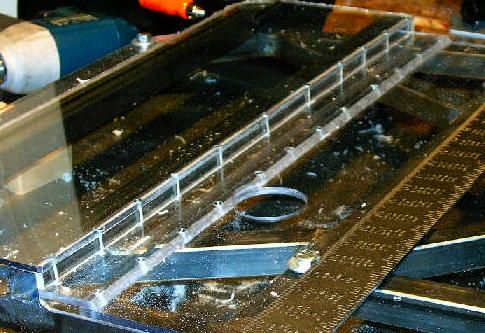
| Also, because I moved the location of the master power switch, I had to drill a new hole so that I can get to it with the top plates bolted on. This hole has to be quite smooth (it's no fun reaching through a small hole with really sharp corners) so I'm going to do it in several passes. The hole-saw tends to heat up really fast when cutting polycarbonate, so I drill for a few seconds and then work on something else while the tooling cools down. |
 |
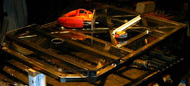
| I worked for a while longer cutting all of the new little bits that I needed and ended up with this. As you can see, I finished the switch-hole and also fabricated four new Lexan pieces. One of those pieces has a 45-degree cut which ended up being a real pain in the ass to finish. It took no less than three tries to get right. It puts a lot of sideways forces on the work-piece which, when coupled with the vibrations, really tends to make jigs come apart. |
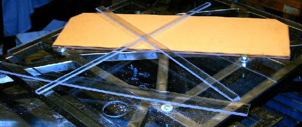 |
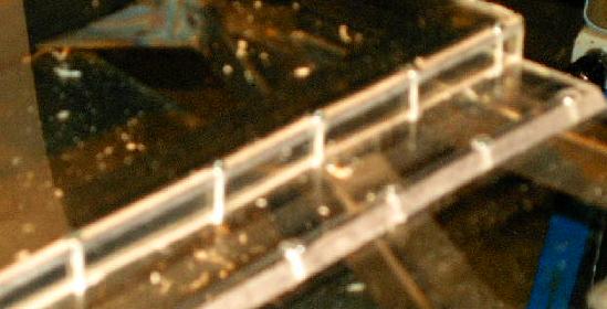
| Here's how they'll fit together to go over the new members. You can see the angled cut on the far right, and you can also see where I've notched it to leave clearance for the switch-hole. Also note that the very top piece (the one still coated in protective paper) is slightly thinner than the others. I used 3/16-inch Lexan for this because of it's small size and relatively simple set of possible load cases. |
 |
| Then I started screwing things together. This was a really labor-intensive process. I masked the Lexan, marked the appropriate intervals, and center punched every hole. Then I drilled a few of them all the way through both sheets with the 7/64-inch drill bit. I then widened out the top hole to 9/64 and then I counter-sunk it. With that done, I ground the point off of the wood screws (there's no need for it with the pilot-hole and I didn't want sharp edges on the other side), and screwed them into the holes. With that done, the two pieces were joined together and I could work on the other holes. Each one required three drill-bits (7/64, 9/64, and countersink) and there were 12 screws just for these two pieces. |
 |
| I think it was worth all the work. These really look nice, and I'm really happy with the strength of the joint. The top surface is nice and flat, it looks cool, and there's good even pressure along the entire seam. |
 |
| Now comes the hard parts. I've got to do the same thing as before but instead of screwing two plates together flat, I've got to do it at a right angle. That means drilling holes lengthwise through Lexan strips. This one actually went fairly smoothly -- some of those holes are a far cry from straight, but they'll work. And, most importantly, I didn't accidentally breech the walls on any of them. |
 |
| This was followed by more of the same. I had to drill slightly larger holes in the top and bottom plates, countersink them, and drive screws to hold everything together. It isn't as strong as the previous seam, but it's a lot better than I could have done with glue. It looks like this method will work just fine, and it looks cool too. |
 |
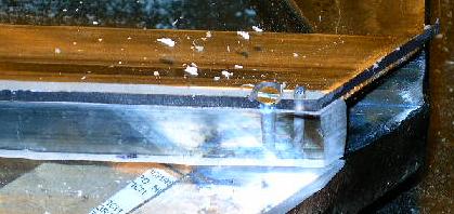
| Here's a close-up on the countersunk screw heads. This didn't come out great because the screw heads are a hair over 1/4 of an inch wide, which means they overhang the edge just a bit. It isn't a big deal, but it would be better if they didn't. |
 |
| The other side didn't go as smoothly. I breached the walls once, which resulted in a really ugly screw-hole. I also broke two drill bits. I couldn't believe how hard these things bound up in the Lexan. The second one I caught before it snapped, removed it from the drill chuck, and tried to carefully extract it with pliers. I tried as hard as I could and I couldn't budge the thing. It finally snapped off from shear as I tried to torque it out. Anyway, here you can see one of the bits. I've simply drilled another hole and put the screw next to it. It doesn't look great, but it will work. |
 |
| All that work and all those screws for this -- a plate with a hump in it. I have to admit that it does look pretty cool and I'm happy with the strength of the whole thing. Looks like this little project was a success. |
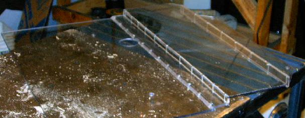 |
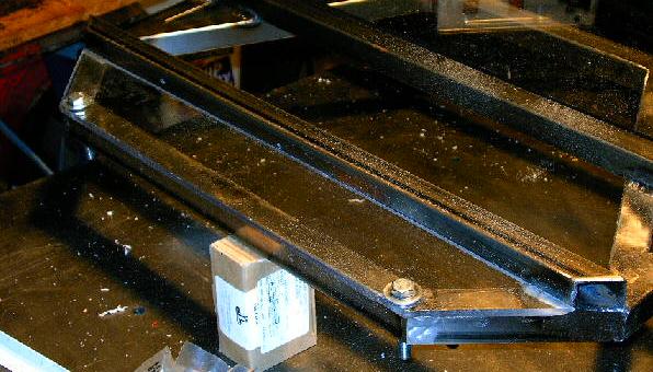
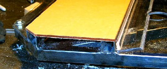
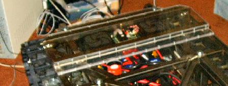
| Here's a good picture that shows how the plate sort of stair-steps over the added height of the speed controllers. This should work great at not only protecting the electronics from debris and impacts but also from water and rain. |
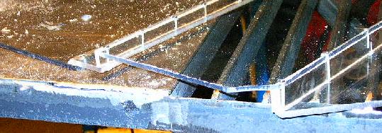 |
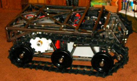
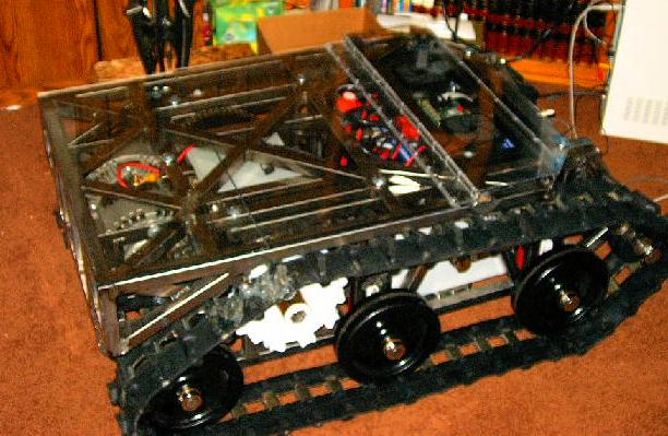
| Here it is on the robot. Looks like everything still fits. |
 |
| Now I just have to charge it up and everything should be good to go. |
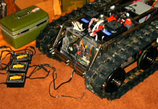 |
| And here she is all ready to go. After this I loaded it into the car and drove down to Implicit Networks Inc where Christina just started working (congratulations babe!) to show it off a little bit to her coworkers. Unfortunately, the laptop started really acting up and we didn't have time to trouble-shoot it properly, so we just opted to show it off in a more stationary fashion. They were impressed with its appearance and stature in general, but it would have been nice to drive it around for them a little. Oh well, maybe next time. We still have yet to take this robot anywhere and have it return to the car under its own power. I suppose some simple network issues are a lot better than major system failure like before. You'll be happy to know that it turned out to be nothing major and everything is now working just fine. |
 |