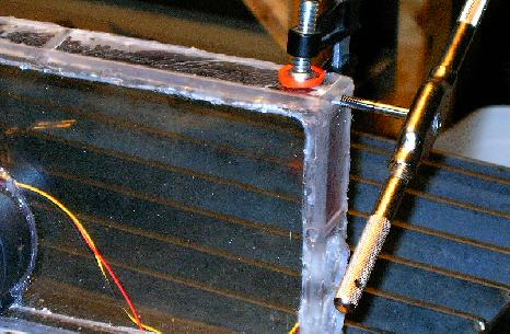
| It's finally time I got to work on the new computer enclosure shock mounting system. I bought some nice rubber vibration control mounts from McMaster and Carr, and now I'm working on setting up the enclosure to accept them. They have 3/4" long studs with 1/4-20 threads, so here I'm tapping matching threads into holes in the top corners of the box. |
 |
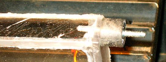
| Here's a shock mount threaded into the holes. Looks great. |
 |
| A little more drilling and tapping, and the top two shock mounts are securely threaded into the enclosure lid. That was the easy part. Now I need to work out the lower mount points as well as all four anchors to the chassis. This ends up taking a couple iterations. |
 |
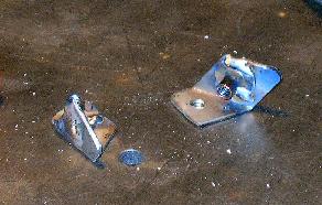
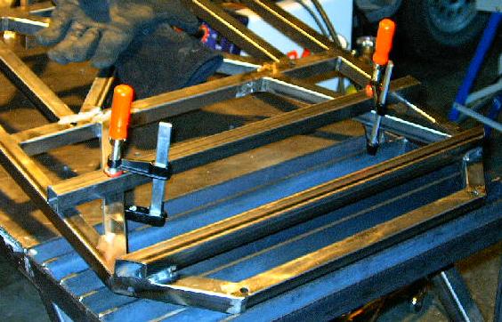
| Here's what I came up with for the top anchor points. They don't look like much, but they were a lot of work. I cut short strips of steel strap, bent them, checked them against the chassis, trimmed them to fit, marked the hole locations, drilled, and welded the weld nuts into place. They sure are ugly little brackets, but where they're going to live, no one will ever see them. |
 |
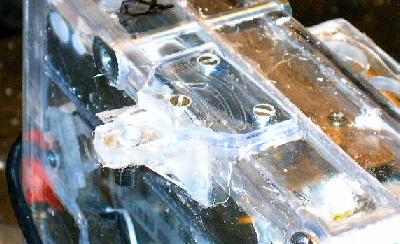
| Now it's on to the bottom mounting points. This little pile of Lexan bits is my first shot at a solution. These will assemble into little angle brackets and be glued onto the back of the computer enclosure. |
 |
| Here they are assembled and glued into place. They look great, but, as I'll find out later, are rather lacking in strength. When I actually try to mount the computer, they have an annoying tendency to break off. I'll end up making better supports for the bracket, but not until I tackle a few other little projects. |
 |
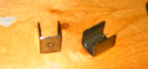
| The final question was how to constrain the bottom vibration control mounts in the slot. Pictured here is the simple solution that I devised. To make these, I simply cut short sections of square tubing, drilled holes in them, and cut one wall off. That left these little steel channels that will constrain the mounts nicely. |
 |
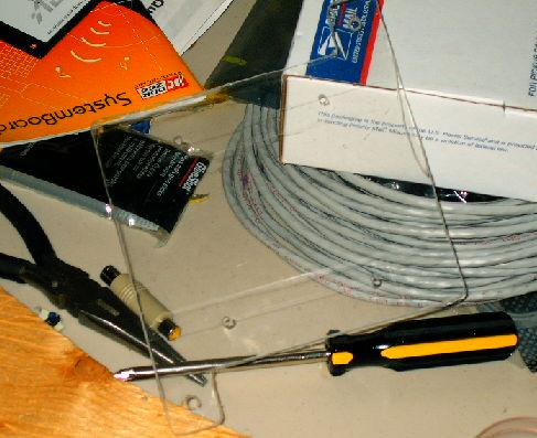
| Nothing makes you appreciate working with Lexan more than accidentally grabbing a sheet of acrylic. I was having a bunch of trouble cutting this sheet (it was melting and clogging up the blade something awful). I thought it was just a dull blade, but as soon as I started drilling the holes I knew I wasn't working with polycarbonate. You see, Lexan is a clear polycarbonate plastic sheet, while acrylic is another form of clear plastic. Lexan, when in the proper thicknesses and laminations, is bulletproof. Acrylic is not. Lexan does not chip or flake. Ever. Acrylic does. Lexan has an extremely high melting point, making it easy to machine. Acrylic melts at cutting temperature, which causes cutting heads and blades to bog down. Anyway, this is acrylic. I'm too lazy to make another one out of Lexan. It doesn't have to stop any bullets, so it should be fine. |
 |
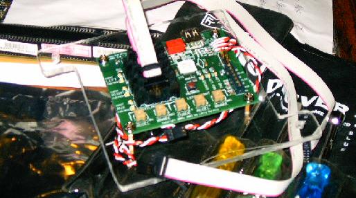
| Oh, yeah. I forgot to mention what that acrylic plate is actually for. It's a mounting plate for my new uMOB2 pulse-width modulation controller board, pictured here. I inserted brass studs into each of the four small holes and used them to screw down the board. This actually added too much height and I had to modify it a bit later, but it was no big deal. |
 |
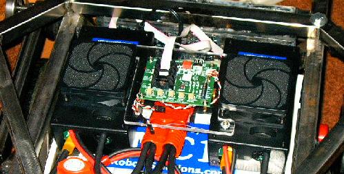
| And here's how it will fit inside the robot. Two screws hold the acrylic plate to the speed controller lids, suspending the uMOB2 in the small gap between the cooling fans. |
 |
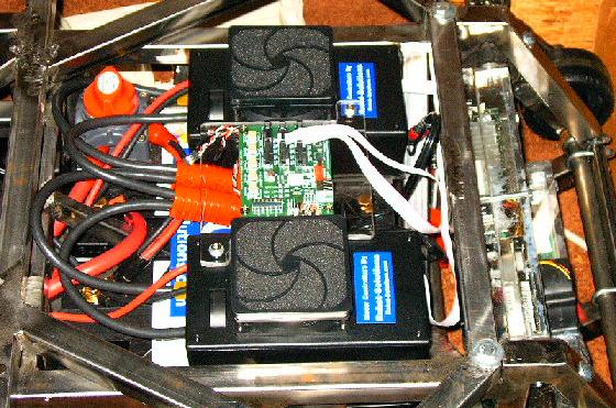
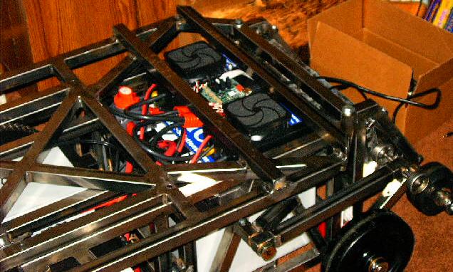
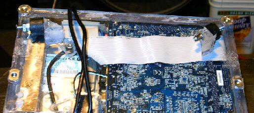
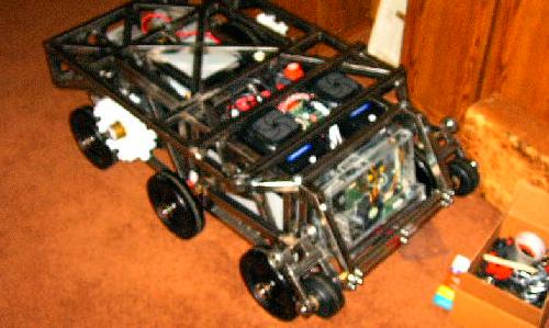
| The electronics compartment in the robot is getting more and more cluttered. I'm going to have to modify the chassis a bit to protect all of these fragile components, but I think I've figured out a simple and easy way to accomplish this. Living in here (above the front two batteries) is the master power switch, main power disconnect, a lot of wiring, both speed controllers, uMOB2 PWM controller, ribbon data cables, and shock mounting for everything. You can also see the computer compartment with new shock mounts on the right. |
 |
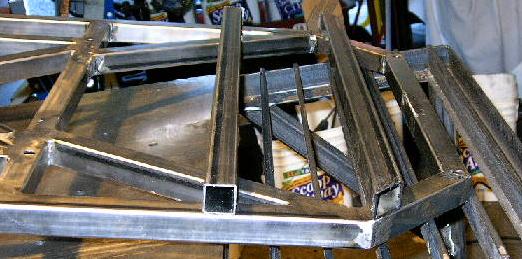
| And here's how I plan to protect it all. These two bars provide a little extra height for the cooling fans to protrude into and should be able to support a great amount of weight without damaging any of the sensitive bits underneath. |
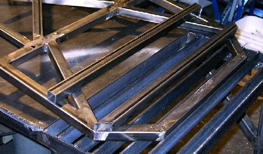 |
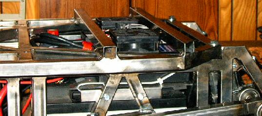
| This picture shows the extra room these two new members will provide for the fans. The fans and the uMOB2 both stick up above what used to be the top plane of the panel. Now, with this modification, they'll live between these members where they'll be protected from harm. |
 |
| Now I just need to start welding everything securely into place. I'll weld the front one down first, because it fits right where the angled member meets the sides. Once it's all done and cooled, I'll line up the other one using the cooling fans as a guide, mark their positions, and then finish the job. |
 |
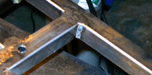
| It's really amazing just how far my welding has come over the course of this project. This is a picture of one of the fillet welds I made on the top panel when I originally constructed it. See how it doesn't really solidly join the two members? It was made too cold (meaning that I move the gun too fast), and didn't penetrate the steel deeply enough. |
 |
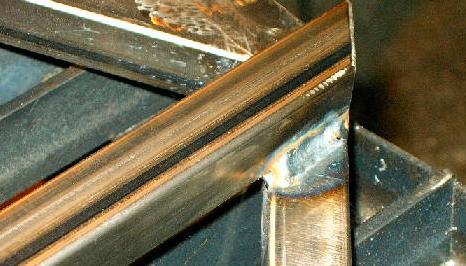
| This is one of the welds I just made. It is much, much better. It penetrates deeply into both of the pieces of steel to be joined and solidly fuses them together. It looks a lot better, too. |
 |
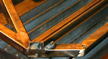
| This setup is remarkable because this almost never happens. Here you see the second member clamped into place very simply with two clamps. There were supporting members in exactly the right places so that it was secure and exactly held in place, I didn't have to worry about melting the clamps (which I do a lot), and I didn't have to work out some contrived system of spacers and dozens of clamps. This is very rare indeed. |
 |
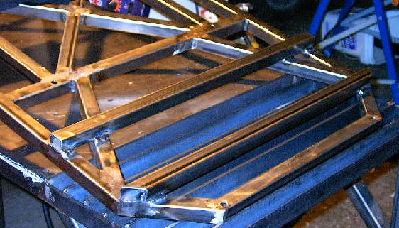
| In this picture both new members are solidly welded into place and cooling. Once they're at a reasonable temperature the top panel will be ready to go back on the robot. While I waited, I took a few minutes to modify the acrylic mounting plate I made earlier. It's a little bit too tall (the uMOB2 sticks out about a tenth of an inch and the USB cable doesn't quite fit). I enlarged the holes for the studs and let them drop down further into the acrylic (sorry, no pictures. It really wasn't very exciting). That did the trick. |
 |
| And here it is on the robot. You can see how the fans stick up into the new little pocket and how everything fits together. It's still a little tight (the USB plug pushes against one of the new members, putting a bit of stress on the uMOB2 board), but I can live with it. |
 |
| Another shot of the same thing. Looking good. |
 |
| With that all wrapped up, it's time to get back to the computer enclosure mounts. Here you can see that both of the lower mounting points have pulled off. It's happened twice, actually. The first time I upgraded to a stronger glue and cut grooves into the surfaces, but that didn't work. Now it's time to get serious. |
 |
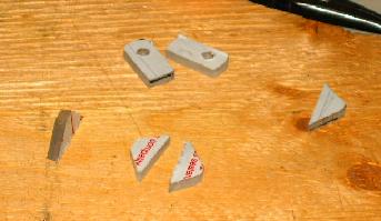
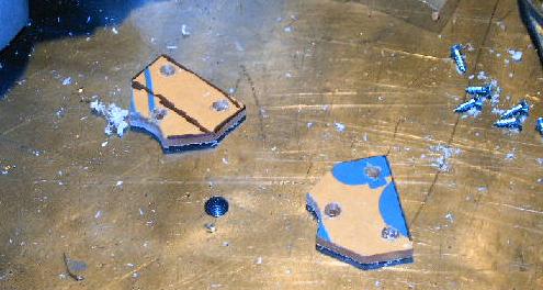
| These are my solution. At first I thought I'd just make little plates to glue along the sides of the enclosure to gain a lot of shear area in the plain of the torque required to install the mounts. After thinking about it for a while I decided that I'd kick it up a notch (BAM!) and add some mechanical fasteners. Ten minutes and I'd cut, drilled, and counter-sunk these little bits. They should fit the bill perfectly. |
 |
| More glue, more drilling, and some screw-driver-ing and I was in business. Looks nice and strong. |
 |
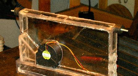
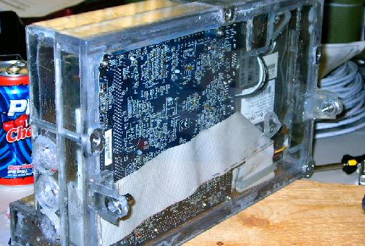
| Here's the computer system all mounted up with it's new vibration control mounts. These are much nicer than the old red polyurethane straps that used to do this job. They were a huge pain in the ass to assemble and disassemble and they weren't as secure as I wanted -- there was the possibility that they'd allow travel in an unexpected direction. This left the outside possibility that the box could impact the front axle. If it was under sudden load at the time, this could cause a strong impact and big problems. |
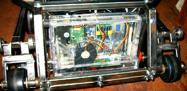 |
| And here's where I'm left after the past few day's work. It's starting to look pretty good. I still have to modify the Lexan top plates to accommodate the new members, but that's not top priority until I want to start driving around in the rain. Now all I really need is to update the software to communicate with uMOB2 and we should be ready to start driving around again. |
 |