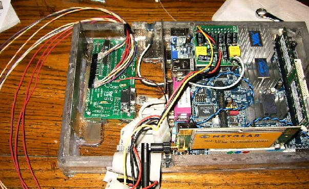
| First thing today, I mounted the PWM board built last time into the computer enclosure. This was a really tight fit, but I managed to make six little Lexan bits that fit the bill. There's 1/4 inch feet under the right two corners of the board and one 3/16 inch foot under the lower left corner (there's a contact right next to the upper right corner, so I've left it floating). I also added Lexan pads on the top side of the board so that I could use the same sized screws on all three corners. I glued everything in, cut a new hole in the box for the power plug to move to, and used its old spot to route the signal wires out. |
 |
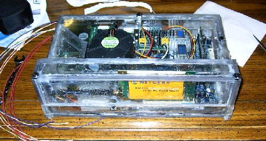
| With it all mounted up, there's just enough room to install the hard disk on top and bolt the enclosure lid on. Looks like it all fits. |
 |
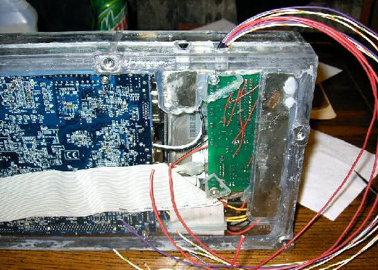
| Here you can see the bottom of the enclosure. This shows the jumper wires I installed in the PWM board to make everything work right, and also a better view of the Lexan feet I made. As you can see, these aren't very professional, but they get the job done. You can also see why I used different heights for the right and left sides of the board -- the left sits on the 1/16 inch thick hard drive mount. |
 |
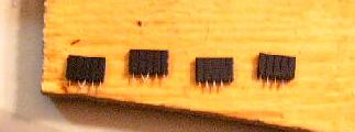
| Now it came time to work on the other end of this little project -- the end that plugs into the speed controllers. They each have a 10-pin connector, arranged in a 2x5 rectangular format. I'm planning on using two rows of five female headers for each connection, and here they are. It's a little hard to see, but I've also bent a pair of pins together on two of these. These will be used for the AHI and BHI logic pins, which are tied high all the time. |
 |
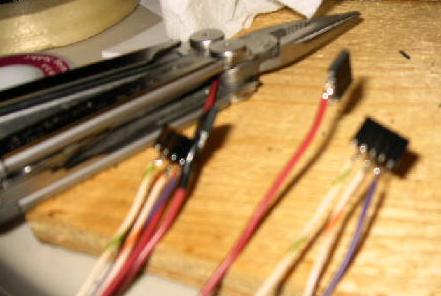
| This was supposed to be a picture of the connections all soldered up, but my camera decided that the part of the picture that should be in focus was the pliers laying on the table. Oh well, I guess you'll just have to use your imagination a little bit. There's one important thing I've forgotten here -- a ground wire. I add one later, but I forget here so it does serve to be a bit of a pain down the road. What is included here is two 5V (red), BLI forward pulse-width modulation signal (green and white), ALI reverse pulse-width modulation signal (orange and white), and disable (purple). |
 |
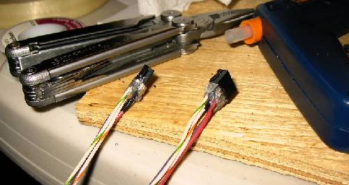
| Finally, I've added some hot glue to the connections to line the pairs of headers up and also to make sure nothing shorts together unexpectedly. |
 |
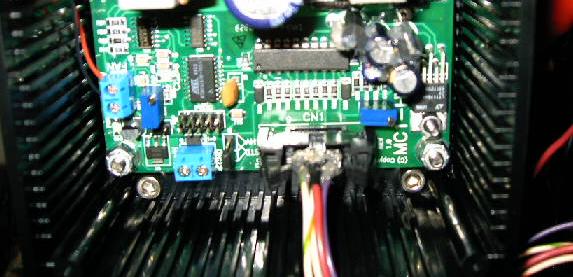
| Here's a close up shot of the plug fitting into the speed controller. It's designed for a special plug with little clamps and everything, but I don't have anything like that. These female headers worked just fine, and they even eject properly using the built-in mechanism. |
 |
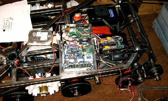
| I slipped the computer into the robot, plugged the controllers into the PWM board with my nice new little connectors, and powered everything up. The controllers came on, the computer cranked up, and the wireless network pung just fine. Then we sent in a PWM signal, and the motors did not move. |
 |
| So, out the computer comes. I cracked open the enclosure and started probing around with the voltmeter. It looks like the PWM is working just fine. |
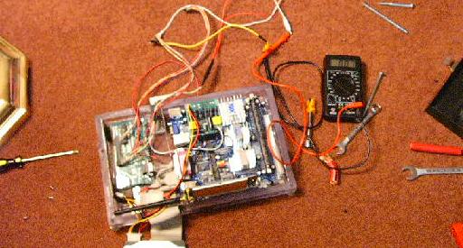 |
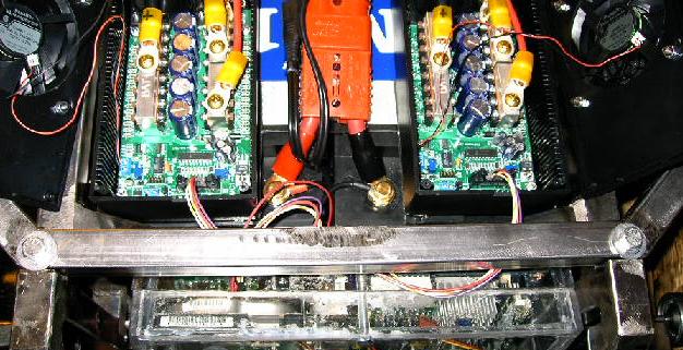
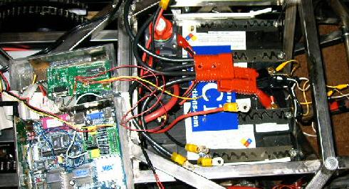
| I wired it back up with everything open so that I could monitor the signal with it hooked up. It stayed in this general configuration for a few days as I tried everything I could think of. The ground pins of everything got tied together into a big common point. I tried different signals at different voltages. Dozens of emails came and went to and from David Moeller, my controller guru. I poured over spec sheet after spec sheet, learning about the integrated circuits within the controller, the layout of the PWM board, and how all kinds of other interface boards were set up. No matter what I tried, the H-bridge never quite operated properly. |
 |
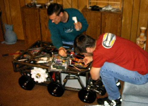
| It was time the gloves came off. I enlisted the help of some friends, who are much better at this kind of thing than I. On the right (in red) is David Star, an electrical engineer who graduated a few terms before I did from Cogswell. On the left (in blue) is Keith Ballantyne, a guru in all things. He graduated one term before me with a computer science degree, but he's worked in embedded systems for years and has been an invaluable resource in almost all aspects of this project when I need help. They poke around inside the controllers for a while and trace down the circuit paths, but aren't able to figure much out. Through working with them, I learned a whole lot about how everything worked (or was supposed to work), but we didn't actually achieve any breakthroughs. |
 |
| I spent another couple days working on things, and I was even able to finally get some diagnosable data off of the output pins of the HIP4081A (the integrated circuit that appears to be causing all the problems), but nothing that I'm equipped to make sense out of. It's become clear that the problem is just beyond my ability to deal with. I'm unwiring the controllers and packing them up. |
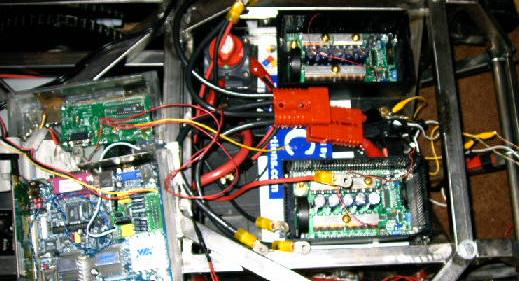 |
| Here's the empty ESC compartment. It's kind of sad, actually -- I was really trying to get this thing working on my own. Oh well, I don't see any way around it now. I'm shipping the controller back to Robot-Solutions for testing. If they find that they're damaged, they'll repair them for me. If they aren't they'll just ship them back with one of their handy little interface boards which I should be able to use just fine. If that's the case, hopefully I'll be able to figure out what the interface board does that I don't. No matter what the case, that's it for my work for the next few days. |
 |