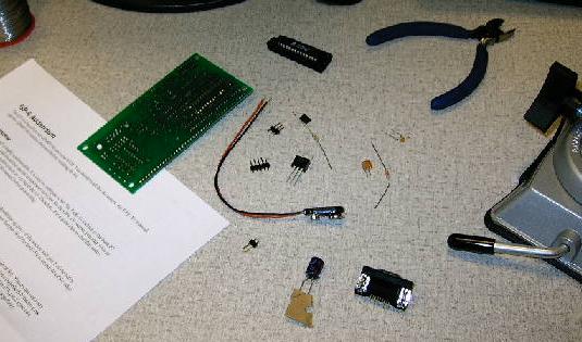
| Today, I spent a few hours assembling our PWM Coprocessor support board, which arrived in a box looking something like this. This would have been a major problem if I hadn't taken an embedded systems course last term. We build our own Handy Boards, and in the process we learned a whole lot about soldering techniques and general electronics construction practices. After that, this shouldn't be too big of a deal (though it is significantly less thoroughly documented). |
 |
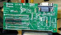
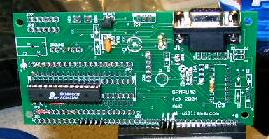
| As it is, I'm reasonably comfortable soldering all of the components to the board, one at a time. I started with the integrated circuit socket, as this was the centerpiece of the entire system. The socket is the little black rectangle with the silver dots on the left side of the board. |
 |
| Next, I added a few small components, mostly resistors. I also jumpered several pins. These steps served to hook up the serial interface to the proper pins on the integrated circuit. This particular chip only needs the ground and data transmission pins, so this was pretty straight forward. |
 |
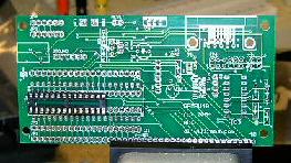
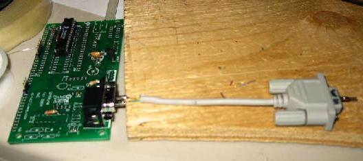
| Speaking of the serial interface, here I've added a right angle female RS-232 port to the top edge of the board. I only need two pins, but I went ahead and soldered all of the connections, just for completeness' sake. |
 |
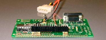
| Here, I've added several things. The easiest to see is the PAK-V PWM Coprocessor itself, which is plugged into the socket (no solder). Another important component is the small yellow bit up from the middle of the board. This is the ceramic resonator, and it will provide the clock pulses (with capacitance built in) to the chip. Also here are a lot more jumpers and the male headers that I will plug the external wires to. Later, we find out that the locations of one of the groups of headers is one off (I'm almost sure the documentation is flawed, but it's always possible that it was my mistake), but we don't know that at this point. |
 |
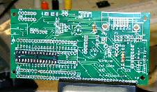
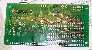
| This is a picture of the back of the board. Here, you can see the majority of the jumper wires that I soldered. This board is a universal integrated circuit (IC) interface, so if you want to use it for a custom application, you have to sort of make do with what you have. This is essentially equivalent to adding a third layer to the circuit board with these wire traces on it, but much cheaper, and a lot bulkier. Looking at this picture, I can actually see the wire traces not lining up right on the pins that are soldered in the wrong place (bottom middle, three pin header, for those of you that are curious). |
 |
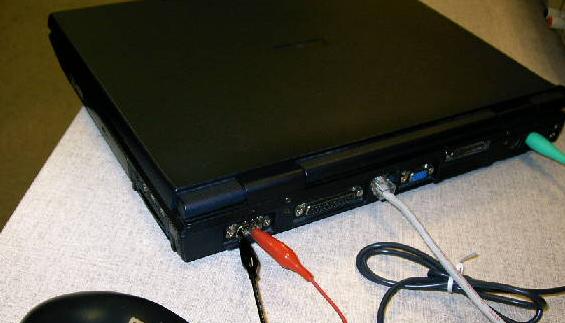
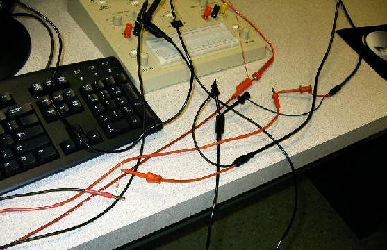
| Now that it seems to be more or less together, it's time to play with it a bit. Unfortunately, the wiring is a bit sketchy, as you can see here. I've clipped a pair of tiny alligator clips to the data and ground pins on my laptop. Hopefully they won't short to anything. |
 |
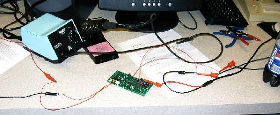
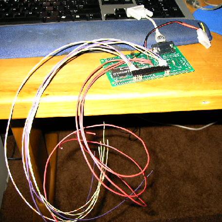
| Here's the first wiring setup, spread all over the table. You can see the leads pictured above coming into the picture on the left and plugging into the serial port. From the right we have the power and ground cables as well as the oscilloscope leads. Sadly, when we tried to do some testing, none of the code was really able to talk to this thing, and it was time to lock up anyway. We called it a day and resolved to come back the next day to get things working. |
 |
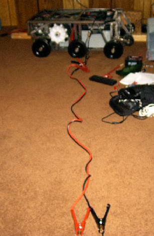
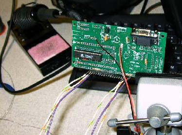
| So, while Christina was researching communication protocols, I got to work rigging up some more reliable wiring. And, of course, what's more reliable than tapping the robot and running cables all the way across the room? Actually, I just needed this for a few moments to pick the regulated 5V off of the computer system's power supply (this was a triple-check -- wouldn't want to screw this one up). |
 |
| Once I had that ironed out, I set up a power supply plug into the board and moved on to work on the serial connection. I don't have a spare male plug that I want to cannibalize for this project, but since I only need two pins, I figure I'll just make one. Here, I've got two pins inserted into the data and ground pins of the board, and these pins have been soldered (using my personal, much cheaper soldering iron) to the appropriate wires. Once this was set up, I encased the bare wire and remaining pin bits with hot glue to make the plug. It isn't pretty, but it should do that job. |
 |
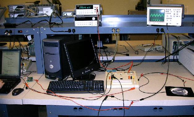
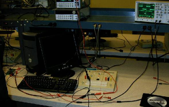
| The next day we set everything back up and got back to work. Here you can see the new, improved wiring setup. The board is right next to the laptop because we're using my homemade two-pin serial cable (which is about four inches long). We also have a power supply hooked up and the circuit output and input are being monitored by the oscilloscope and the digital multimeter. |
 |
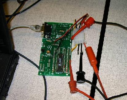
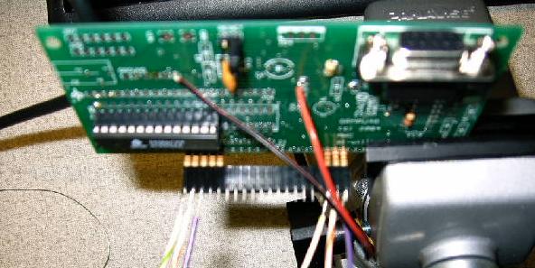
| Here's a close up of the board itself. You can see the two-pin plug as well as the power supply port used for the master power. The oscilloscope is hooked up as well, but we haven't started generating any signal yet. |
 |
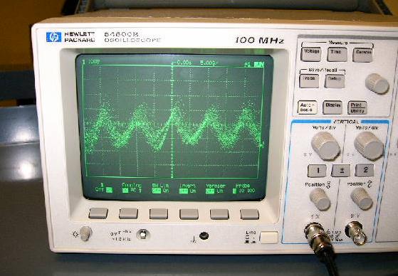
| Here's the initial oscilloscope reading. That is nothing but line noise. We've got long leads running from the scope to the board, so they're picking up a lot of cross-talk and other wayward signals. The horizontal grid lines are in divisions of (I think) 0.01 volts, so this is nothing to be alarmed at. |
 |
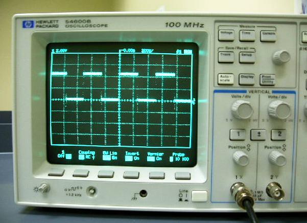
| And here's what we wanted it to look like. That's a nice square wave, and the y-axis is now set at 2-volt divisions (making this wave just shy of 5V). There's only one problem: we told it to do about a 10% duty-cycle, and that's closer to 60%. Christina tinkered around with the thing for a bit, and found a small bug in the code that encoded commands before it sent them out. It was easily fixed, and we were back in business with much more reasonable values. |
 |
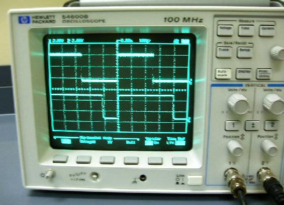
| We decided to make sure the thing could multi-task like we wanted it to, so we asked it (very nicely) to produce two PWM signals simultaneously. Looks great. We've got one 50% duty-cycle and one 80% (this was the point, by the way, when we figured out the output pins were soldered in the wrong place -- the signals weren't being produced on the pins we expected). This plot also serves to juxtapose a filtered and unfiltered signal. On top you can see the direct output of the chip -- each transition in state causes an overshoot spike that oscillates down to equilibrium (hence the noise factor that makes the lines look thicker). The bottom you see the filtered signal. The changes in state on that one aren't straight up (you can barely see the slight radius on the corners), so it appears much smoother. |
 |
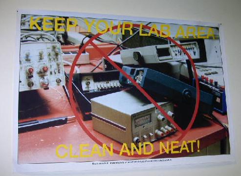
| This poster has been hanging on the wall of the electrical engineering lab at Cogswell for at least the four years I've been going there, and we've always joked about it. It's supposed to show a messy workstation as an over-the-top example of how not to do things, and the station is just not that messy. It looks like someone just stacked a few devices up and took a picture -- there aren't even any wires. |
 |
| Now this is getting closer to what I picture when you say "messy work station." At least, it's a start: I've made much bigger messes in this lab. I suggested to the lab manager that he might want to take a picture of my work and make a new poster. |
 |
| This big heap of wires just provides the power and signal for the board, and incorporates one 22k resistor into the signal wire to filter it a bit. That's all. See how quickly the wiring gets really complicated and messy looking on this kind of thing? Imagine if there was actually someone in here working who knew a thing or two about electrical engineering -- I'm sure they could make a much better mess than that poster. |
 |
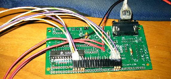
| At this point we knew that the chip worked just fine and dandy, so it was time to get everything sured up for final wiring. First, I had to remove the header that was soldered in the wrong place. While I was at it, I went ahead and removed all the headers on the output lines and replaced them with 22k resistors (I decided that I liked the filtered signal better). You can see here the eight of them along the bottom edge of the board (one group of five and another group of three). |
 |
| Into the headers that fit over the resistors, I soldered six long wires that will serve as the actual data cables for this coprocessor. Three data wires will go to each controller (purple, green, and orange). I'll also need a five volt wire for a few pins, but that doesn't need to come from this rail. |
 |
| Another shot of the above (this one didn't come out very well). I went ahead and left a long bar of headers connecting the two sets of contacts because I though it would be a little bit stronger. Now I can just pull the whole black plug out of the board and it will keep all of the wires lined up just right. |
 |
| Then, I added some long wires to the positive power rail and started thinking about mounting. This little thing is going to live underneath the hard disk within the already very cramped computer enclosure. There wasn't quite enough room for the mounts, resistors, female headers, and the wires, so I bent the headers over. That should provide enough clearance. |
 |
| It isn't the prettiest thing I've ever built, but if it will fit and do the job, I'm perfectly happy. Now all I have to do is mount it in the enclosure, wire it to the controllers, and rig and kill switch. Those, however, are tasks for another day. |
 |