|
Build Report #50 (05.17.2005)
| Today, the new speed controllers showed up. This meant that it was finally time to really get to work. We won't be able to get the robot working again until our PWM driver gets here, but there's a lot of mounting and wiring work to be done. First, I drilled four holes in each controller's enclosure and eight holes in this mounting plate (you can't really see them, but they're there). I also bought a bunch of screws to hold everything together. |
 |
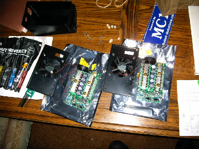
| Of course, before I could start drilling holes in the enclosures and mounting plate, I had to liberate the circuit boards. This picture shows the creamy centers of the speed controllers carefully nestled on static-bags while I worked on the mounting issues. It's a little nerve-wracking pulling these things apart, but they seem to be really well built. I guess if they can survive combat, they should be just fine being lovingly lifted out of their protective boxes. |
 |
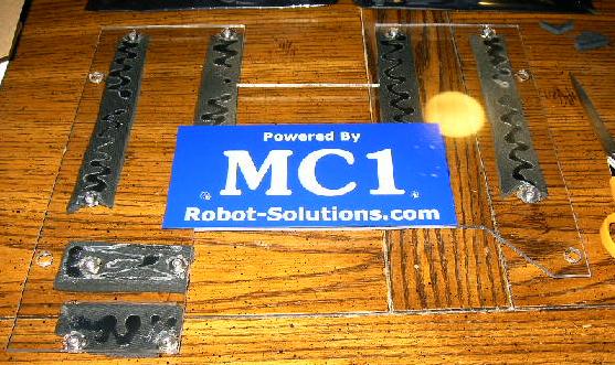
| I peeled the protective paper off of the mounting plate, slapped a Robot-Solutions sticker on it, glued nuts into the mounting holes, and glued on strips of mouse pad to provide some shock absorption. I would usually wait until a company had really proved itself to me before I put it's name on my robot, but I made an exception for two major reasons. First, David Moeller has really impressed me with his quick, informative, and patient responses to my incessant questions. Second, this mounting plate was designed specifically for these controllers, so if they do blow up and I decide I don't like them anymore, I won't use this plate anymore either, so the whole thing will be moot. |
 |
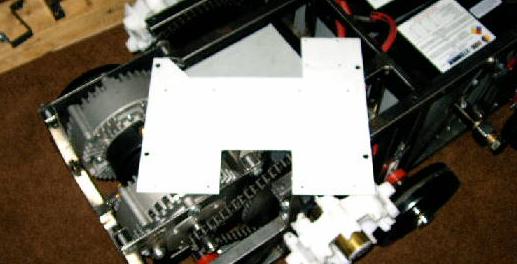
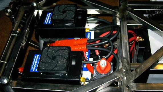
| Here's how they'll mount into the chassis. I had other pictures of this, showing the clearance around the edges and how far they stick up out of the top, but they came out horrible. I just got a new digital camera, and I'm still working out some of the bugs. It's pretty good most of the time as long as I'm careful to use the right settings, but sometimes the images just come out really dark for no particular reason. |
 |
| Now it's time to start wiring. Anderson Powerpole makes some great connectors, but unfortunately I can't just run to the hardware store and pick up some new contacts. I could, of course, order more, but I'm a very impatient man, so I just end up reusing my old ones, which makes for some really ugly crimps. These have already been reused once, and now I'm going to pry them open and use them again. It's a pretty big job, but it's better than waiting for a package to get here. |
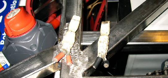 |
| A bit of work and I've got a perfectly serviceable connector. Because I'm now using single channel controllers, I need to get the same battery power to them both. Rather than wire each controller to the battery terminals, I've just wired up this big splitter; it should do the job quite nicely. |
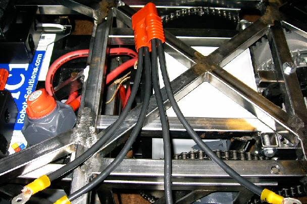 |
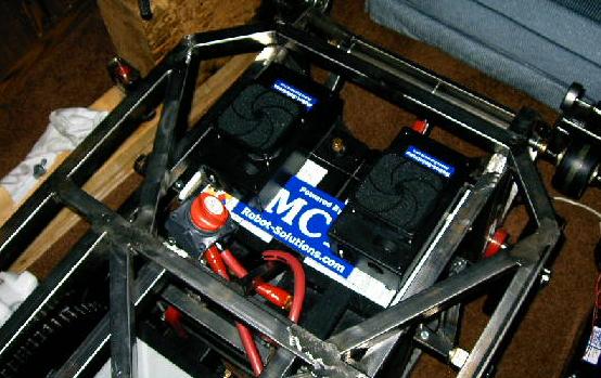
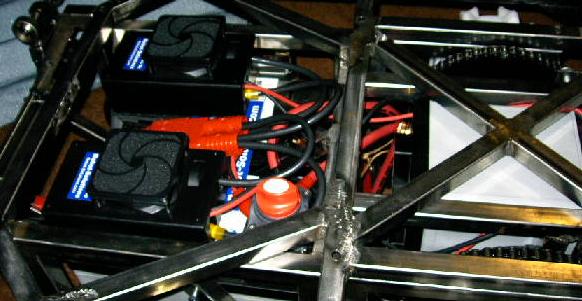
| Here the controllers are wired to the batteries. With this all set up, I get to actually turn them on for the first time. I just throw the master power switch, and the fans hum to life, letting me know that I haven't accidentally grounded anything that wasn't supposed to be grounded or anything. I can get pretty stupid when it comes to wiring, so these kinds of validations are really nice. |
 |
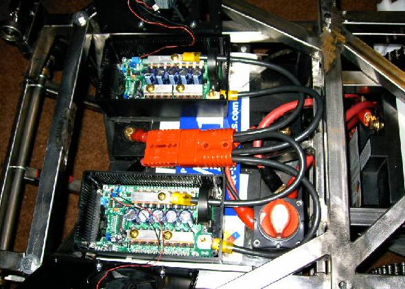
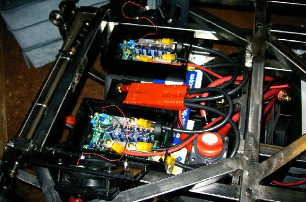
| Here they are opened up so you can see how I wired the controllers. Each of those big chunks of aluminum has a bolt set into it that is used to clamp on a ring terminal. There's also a post for the ground, which is just set into a massive contact on the board itself. |
 |
| Because there just wasn't enough wiring crammed into that rat's nest, I got to work wiring the motors up. To start off, I'm going to continue to use the long 8 gauge wire, which is significantly undersized for the application. The idea is that this will add a bit of resistance and inductance to the motors, making things easier on the controllers, but slightly less efficient. Worst case scenario, we'll have heat problems and need to beef it up, which is no big deal. Well, actually, worst case scenario is that we have enough heat problems to start a fire. Even so, it'd probably just destroy the wires and that would be the end of it. |
 |
| And here it is, all wired and running. I'm pretty happy with the progress for today. The new controllers are shock mounted and wired. Now all I need to do is wire the data connection and new interface board (whenever it gets here) and double check the signal quality and reliability on an oscilloscope. Then, once Christina gets the code all updated for the new configuration, we'll be ready to start testing. I can't wait. |
 |
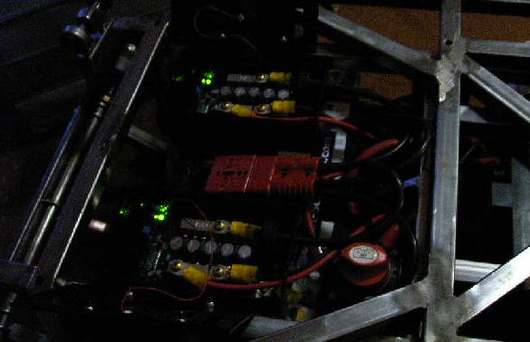
| I took another picture of the above without a flash so that you can see the little LED in each controller that lets us know that they're alive. |
 |
| End, Build Report #50 (05.17.2005) |
| Progress: |
Shock mounted and wired the new speed controllers. |
| Time: |
8 hours |
| Next Steps: |
Build and test the PWM interface board. |
|