|
Build Log, Day 1 (01.17.2005)
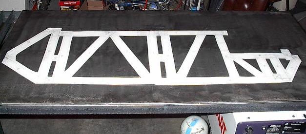
| This is the first of many measures I have taken in the process of paper-aided design and manufacturing (PAD/PAM). This is something I ran across while reading build-reports of some BattleBots builders who were working with extremely limited budget and tools, and so it should be perfect for me. Essentially, this is the poor-man's CAD/CAM process, and it works surprisingly well. The philosophy goes something like this: without tight-tolerance tools and equipment, it can be tricky to build something that actually resembles what you've designed. Those with access to sophisticated computer-aided systems aren't really burdened with this problem, but for those of us who aren't as well equipped, we have to get creative. That's where the paper comes in -- paper is easy to work with and easily transferable. Because of this, I've created several full-scale templates out of paper, which I can then accurately transfer onto the steel. Hopefully, this will keep my tolerances down and prevent what deviation I have from compounding on itself. This picture shows a full-scale layout of the side of the robot's chassis, which I have laminated onto my work table. I'll build the structure directly on top of this image. |
 |
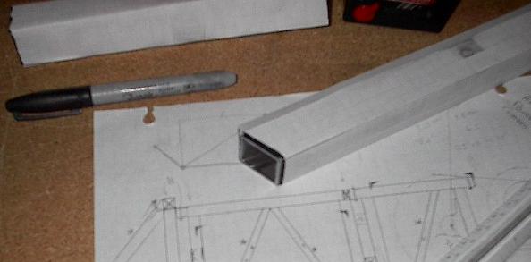
| Now that I have a nice picture to lay everything out on, it's time to cut up the steel. To keep things reasonably accurate, this is going to be a two-stage process. First, I'm going to use paper templates that I've prepared of each member to cut out a rough shape, slightly oversized. Following this, I'll mark them using my most precise templates, and grind them to size. This picture shows me marking the steel with a rough template. |
 |
| Here I've rough-cut most of the nice, easy, square-edged members and laid them out. The angled stuff should be a bit harder, but there's no time like the present. |
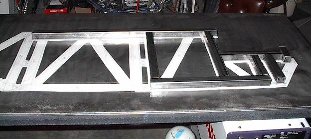 |
| Here's all the rough cut pieces for the side panel. You can see a lot of them don't fit, but that's good. I want everything to be slightly oversized at this point. I can grind extra material off, but it's harder to build it up. |
 |
| Believe it or not, this picture is two hours worth of work after the previous one. I went after each and every piece of steel with a carbon steel wheel brush and took off all of the scale, grime, and surface burrs. I also labeled each piece so I could keep track of them. These members are all ready to be marked and ground to their final shapes. |
.JPG) |
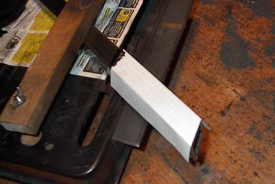
| Here's a picture of one of my most precise paper templates. Really, it's just a square paper tube, but it's easy to make them exactly the dimensions that I want the steel to be. I just have to wrap this around a member and trace the ends to get exactly the shape I want. |
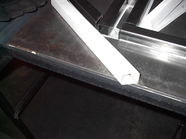 |
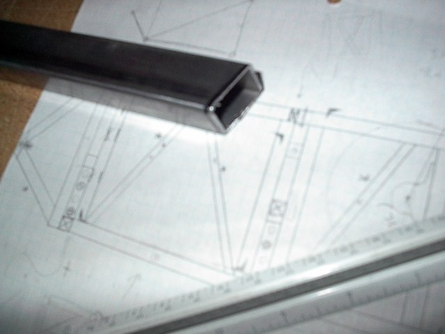
| Just in case you couldn't picture it, this is how you wrap a piece of paper around a square tube and trace the end. Thrilling, isn't it? |
 |
| And here's the result. Now all I have to do is take this to a grinder and grind until the little black ring around the throat of the tube is all gone. Then I should have all of the angles just right. Given that it can all be done with a chop saw and a grinder, this method given just about as high a level of precision as I could hope for. |
 |
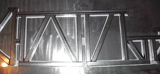
| The result of build day number one: a pile of steel pieces. A little grinding, some welding, and a lot more grinding and this should all amount to one of my chassis walls. I sure have a long way to go, but this is a good start. |
.JPG) |
| End, Build day #1 (01.17.2005) |
| Progress: |
Cut and cleaned most of the steel for one chassis structure plane. Marked pieces for final fitting. |
| Time: |
5 hours |
| Total Time: |
22 hours |
| Next Steps: |
Cut and mark the steel for the matching side. Grind all pieces to shape and weld. Grind and clean these structures and assemble into chassis framework. |
| Status: |
On schedule |
|